Fuel Injector Test
How To Test Fuel Injector
Helpful Information
When a fuel injector malfunctions it can allow an excess or minimal amount of fuel into the engine causing engine run-ability problems. The fuel injector is designed with a pintle valve that allows fuel to flow as a spray pattern while the computer provides opening signals in prescribed amounts regulating volume.
A common misconception about cylinder misfires is they cause the engine to run rich, in the absence of combustion the cylinder contains 14 parts air to 1 part fuel (14:1) which causes a lean condition.
When a system trouble code scan is performed detection of a sensor failure is not guaranteed, a crankshaft position sensor for example, is difficult for the computer to detect.
If injector pulse is not detected, and computer system is powered up with all obvious sensors and wiring checked or replaced, try disconnecting all non-essential sensors, example: oxygen sensor, coolant sensor, throttle position sensor, air intake temperature sensor, mass air flow or map sensor and EGR valve pressure differential sensor and see if the injector pulse returns, one of these sensors could be shorted causing the system to not operate.
Tools and Supplies Needed
- Test light or voltmeter
- Small standard screw driver
- Wrench set
- Socket set
- Protective eyewear and gloves
- Shop towels
- A fuel injector is subject to high temperatures that can cause failure. Each injector has specific ohms resistance reading that is used for testing.
- Moisture can cause the injector connection to short circuit.
Step by step guide on how to test an automotive engine fuel injector, this information pertains to electronic fuel injected vehicles, not direct injection.
A fuel injector has two main sections, the electrical portion which activates the valve assembly and allows fuel to enter the engine. This guide will check both aspects along with the trigger and power circuits supplied by the computer.
Difficulty Scale: 4 of 10
Begin with the vehicle on level ground with the engine off and the parking brake set. Fuel maybe present during these tests, usual fire precautions are necessary. Use protective gloves and eyewear for safety.
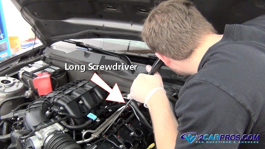
Step 1 - Start the engine and allow to idle, using a long metal rod like a screwdriver touch the end of the rod to the injector, gently lay an ear to the opposite end of the rod or handle to observe an audible clicking sound, repeat this procedure across all injectors, this can help pinpoint the failing injector. (Note: This sometimes can be difficult because of internal engine noise.)

Audible Fuel Injector
Step 2 - With the ignition key turned to the "ON" position without starting the engine, connect a test light to the negative side of the battery and probe the injector wires, one of the wires should illuminate the test light. If a volt meter is used the multimeter (voltmeter) should bounce from 0 to 12 volts. If system power has been disrupted suspect an injector or computer fuse, broken or shorted wire or bad computer, (Note: Seal test points with a small dab of silicone rubber once testing is complete) this test can also be performed with the connector removed as well. Some vehicle computer feed wires are located near the battery, corrosion can stop the voltage feed. If all power sources check out the computer system ground needs to be checked, this is done by reversing the test light lead by installing it on the positive side of the battery which will cause test light to illuminate when grounded, most system ground wires are black but to be sure an online auto repair manual is needed. If repairs have recently been made a system ground lead could have been left off of the engine causing the system not to power up, double check all engine wiring harness grounds.

Test Light Probe Injector Wiring
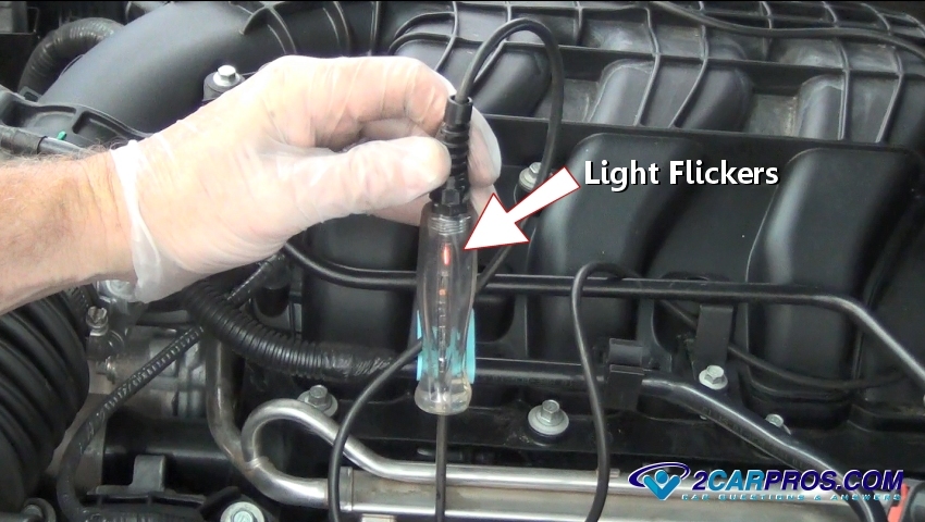
Step 3 - While the test light clamp is on the positive side of the battery, move the test light probe to the opposite wire in the injector connector, have a helper start or crank the engine while observing the light, when cranking or under load the light will flash brightly, when idling or easy throttle the light will flash more dimly. This trigger circuit for the injector is supplied by the computer and follows the throttle and engine demand. If these test revealed that there was no pulse and the computer has power and not generating a fuel injector trigger signal suspect a crank angle sensor, (engine not running) or shorted computer or sensor. A shorted injector can hinder the injector driver operation for additional injectors, unplug all injectors and re-test pulse trigger, if pulse returns, plug the injectors back in one at a time until the pulse fails, replace the shorted injector. If tests check okay, proceed to next step.

Test Light Flash
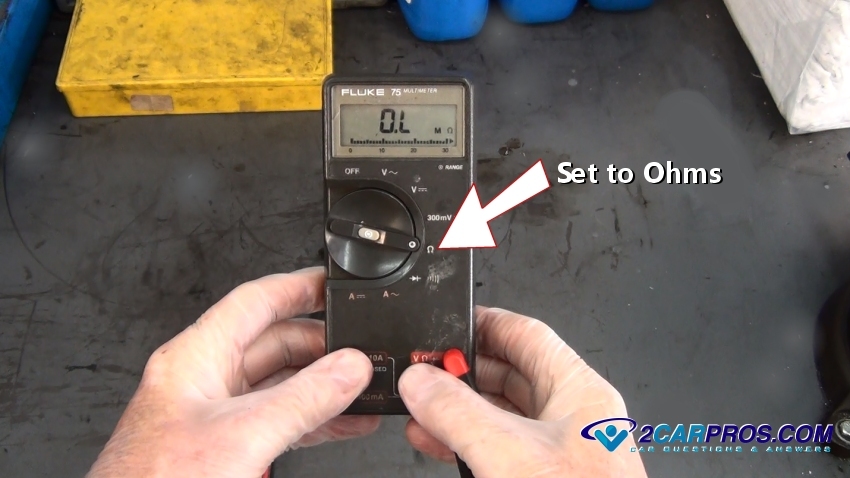
Step 4 - A voltmeter is used in this test, adjust the meter to the ohms setting, these next steps can be performed with the injector installed or uninstalled.
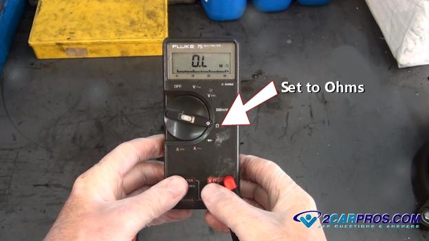
Multi Volt Meter Set To Ohms
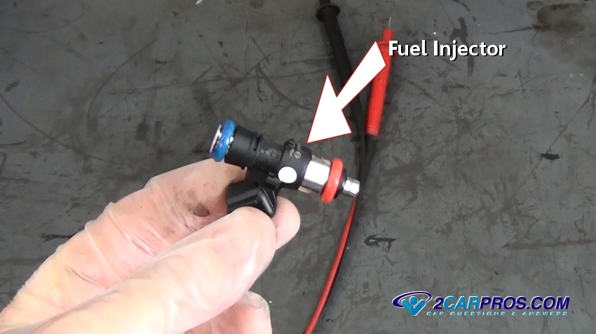
Step 5 - Identify the injector to be tested and inspect for defects or bad connections.

Fuel Injector
Audible Fuel Injector
Step 2 - With the ignition key turned to the "ON" position without starting the engine, connect a test light to the negative side of the battery and probe the injector wires, one of the wires should illuminate the test light. If a volt meter is used the multimeter (voltmeter) should bounce from 0 to 12 volts. If system power has been disrupted suspect an injector or computer fuse, broken or shorted wire or bad computer, (Note: Seal test points with a small dab of silicone rubber once testing is complete) this test can also be performed with the connector removed as well. Some vehicle computer feed wires are located near the battery, corrosion can stop the voltage feed. If all power sources check out the computer system ground needs to be checked, this is done by reversing the test light lead by installing it on the positive side of the battery which will cause test light to illuminate when grounded, most system ground wires are black but to be sure an online auto repair manual is needed. If repairs have recently been made a system ground lead could have been left off of the engine causing the system not to power up, double check all engine wiring harness grounds.

Test Light Probe Injector Wiring
Test Light Flash
Multi Volt Meter Set To Ohms
Fuel Injector
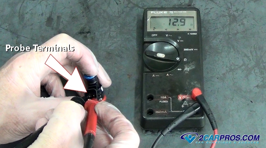
Step 6 - Connect the meter to either terminal of the injector (non specific) to obtain a reading. This test gives a baseline ohm reading of all injectors to be tested, a service manual also has this information. (Note: Injectors should be tested cold unless otherwise specified, temperature will change readings.) If the injector tests produce high resistance or an open circuit, the injector needs replacement. Most injector readings will range between 11 and 24 ohms.

Probe Injector Terminals
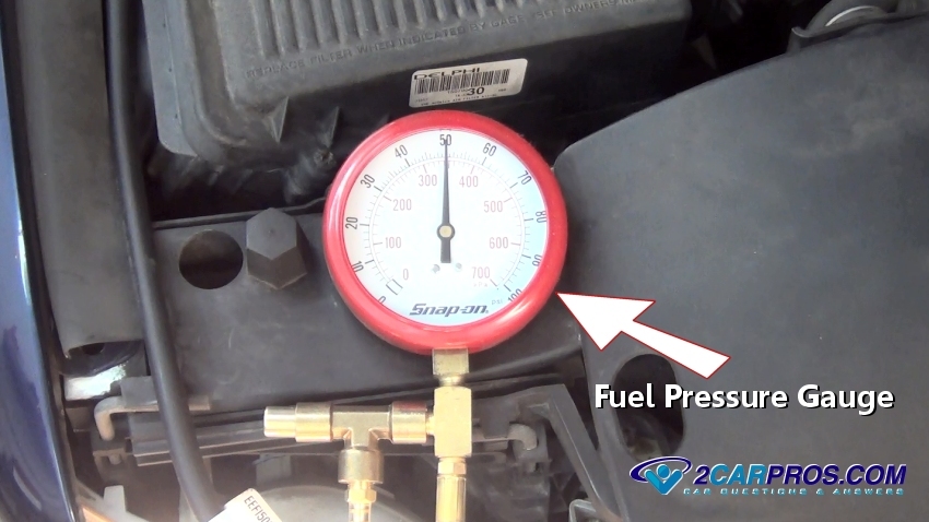
Step 7 - To test the fuel injector valve while installed, a fuel gauge is connected to the fuel system via a fuel rail port or fuel filter. Turn the ignition switch to the "ON" position without starting the engine, this will pressurize the fuel system, then pinch off the inlet and outlet rubber hoses to hold pressure in the fuel rail. (Note: Some fuel systems are designed with an inlet hose only.)

Fuel Pressure Gauge
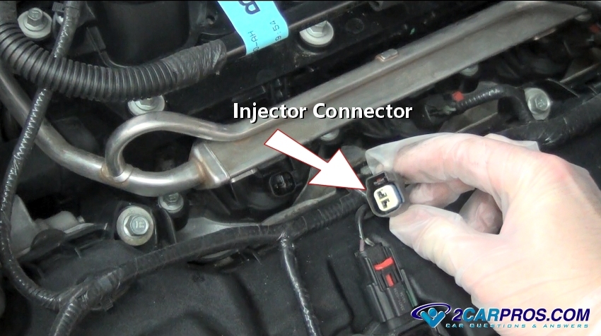
Step 8 - Then, remove the electrical connector from the injector in question for inspection, clean corrosion and rust.

Injector Connector Removed
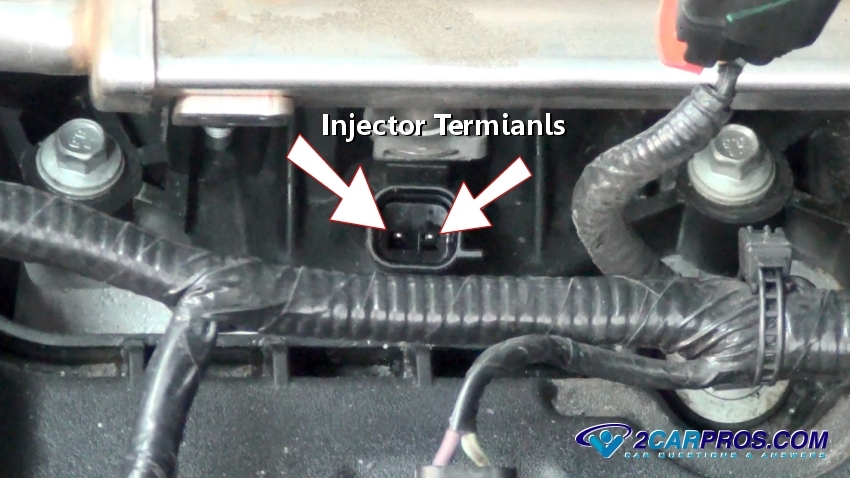
Step 9 - Removing the injector connector will expose the terminals, carefully attach a 12 volt power (power and ground) source to the injector. An audible click from the valve opening while simultaneously observing an immediate drop of fuel pressure at the gauge confirms proper operation of the injector.

Injector Terminals
Step 10 - For a final check, remove the injector and attach pressured air to the injector inlet, then use a 12 volt power and ground source to energize the injector, compressed air should be released from the outlet valve. (Note: Traces of fuel will be expelled as well, use typical fire precautions.)

Injector Discharge
Probe Injector Terminals
Fuel Pressure Gauge
Injector Connector Removed
Step 9 - Removing the injector connector will expose the terminals, carefully attach a 12 volt power (power and ground) source to the injector. An audible click from the valve opening while simultaneously observing an immediate drop of fuel pressure at the gauge confirms proper operation of the injector.
Injector Terminals

Injector Discharge


Comments
Post a Comment