How To Replace Mass Air Flow Sensor MAF
Mass Air Flow Sensor Replacement MAF
Helpful Information
After starting the engine post sensor replacement, the sensor instantly calibrates itself so there is no learn time required. This sensor is subject to debris and contamination which can be avoided by cleaning the sensor (Note: Some sensors are located inside the air filter housing, not all cars are equipped with a mass air flow sensor, consult a repair manual for exact component location.)
Best Practices
Best Practices
- Clean the air intake tube and connection points to ensure proper installation.
Step by step guide on how to replace an automotive mass air flow sensor, this information pertains to most vehicles though applications may vary.
Difficulty Scale: 2 of 10
Begin with the vehicle on level ground, parking brake on, engine off.
Step 1 - When replacing a mass air flow sensor, first locate the sensor which is positioned in the air intake tube between the air filter housing and throttle body.
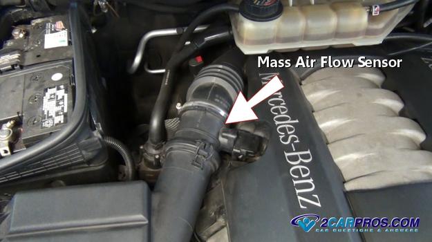
Mass Air Flow Sensor
Step 2 - Release the safety clip and gently pull the connector from the sensor.
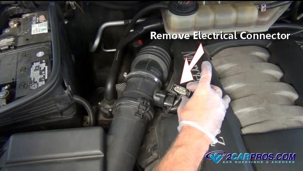
Remove Electrical Connector
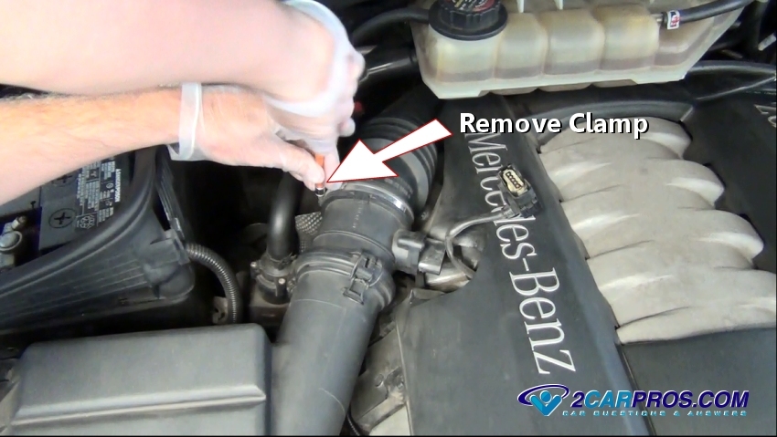
Step 3 - A clamp is used to attach the sensor to the air intake tube, use a screwdriver or small socket and loosen the clamp.

Loosen or Remove Clamp
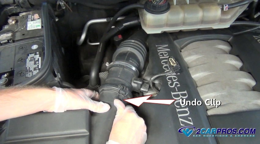
Step 4 - Next, undo the inlet clip on both sides. There are many methods of holding the MAF in place, the principle is the same.
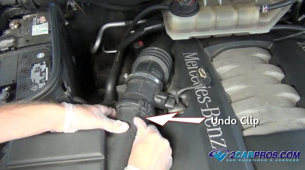
Undo Mounting Clips
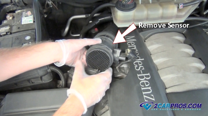
Step 5 - Once all mounting clips or bolts have been undone, lift the sensor and remove it from the engine bay.

Remove Mass Air Flow Sensor

Mass Air Flow Sensor

Remove Electrical Connector
Step 3 - A clamp is used to attach the sensor to the air intake tube, use a screwdriver or small socket and loosen the clamp.
Loosen or Remove Clamp
Undo Mounting Clips
Remove Mass Air Flow Sensor
Step 6 - After the sensor has been removed, inspect internal parts and electrical connector for damage.

Mass Air Flow Removed
Step 7 - Then, compare the old sensor to the replacement unit, they should match identically. (Note: remove dust caps before installation.)
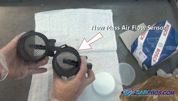
New Mass Air Flow Sensor
Step 8 - Gently reinstall the sensor into the inlet and outlet tubes, ensuring a proper seal between the sensor and the tube.

Reinstalling Mass Air Flow Sensor
Step 9 - After connecting the sensor to both inlet and outlet tubes, tighten the clamp and attach the clips.

Reinstall Clamp and Tighten
Step 10 - Then, reattach the sensor electrical connector ensuring a small click, when completely connected.
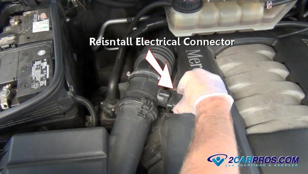
Reinstall Electrical Connector
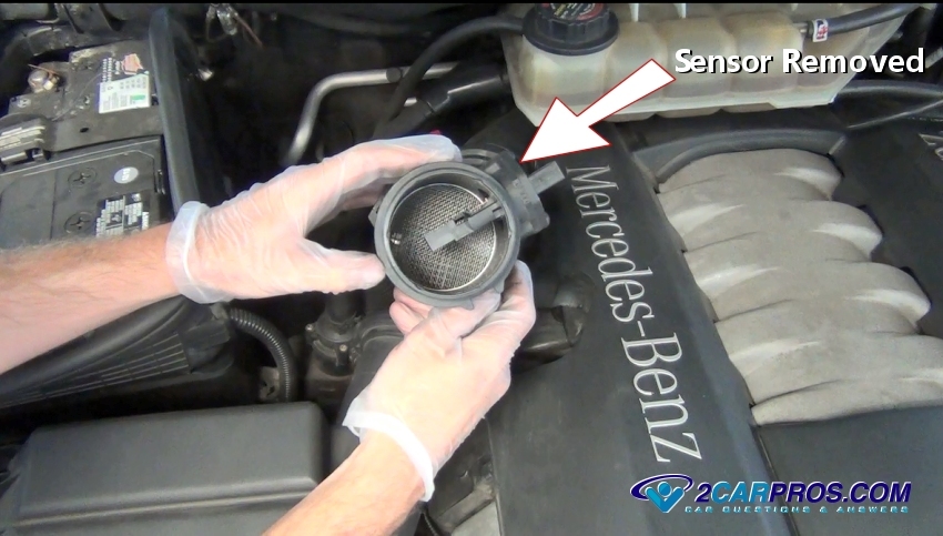
Mass Air Flow Removed
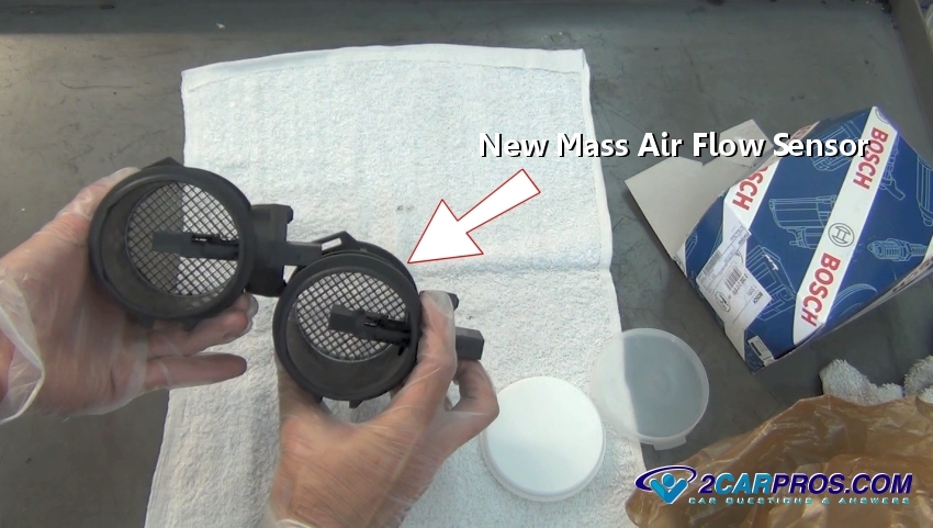
New Mass Air Flow Sensor
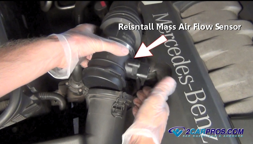
Reinstalling Mass Air Flow Sensor
Step 9 - After connecting the sensor to both inlet and outlet tubes, tighten the clamp and attach the clips.
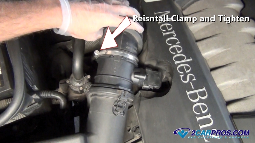
Reinstall Clamp and Tighten

Reinstall Electrical Connector
Step 11 - Once the sensor has been replaced, attach a code reader to the ALDL connector.
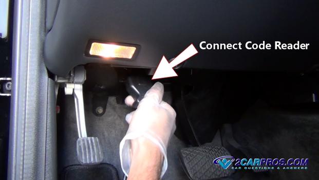
Attach Code Reader
Step 12 - Turn the ignition key to the "ON" position and follow the prompts to clear any codes in the system.
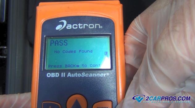
Clear Codes

Attach Code Reader
Clear Codes


Comments
Post a Comment