How An Ignition System Works?
Ignition System
Working Of Cars Ignition System
Helpful Information
An ignition system is designed to ignite a fuel mixture inside the engine's combustion chamber at an optimal time in the piston stroke to produce the most power while emitting the least amount of emissions as possible. There are many configurations of ignition systems but all operate on the same principle, create a low energy field and collapse it onto a high energy coil and that transfers the electrical energy into the secondary ignition system, i.e. coil wire, distributor cap and rotor (if equipped) plug wires and finally the spark plug. This system is triggered by the primary ignition system, this system varies depending on manufacturer but all operate on the same principle, use a low voltage trigger system i.e. crankshaft position sensor (CKP), camshaft position sensor (CAS) to trigger a high voltage spark. This low voltage system (1.5 to 3.0 volts) is amplified to 12 volts by using an ignition module (amplifier) and then transferred to the secondary side of the ignition coil.
This efficient system does not need adjustments or calibrations of any kind. The system is designed to automatically make timing adjustments via the computer program, while accounting for all variations of engine demand. If a misfiring problem has occurred, check the ignition system by reading trouble codes, and testing theignition coils. Worn ignition components can cause the vehicle to misfire which could indicate a tune up is needed. When an engine misfires under power its typically caused by the ignition system. Proper maintenance can help ensure the ignition system operates at peak performance.
There are many configurations of ignition systems, but all operate on the same principle, create a low energy field and collapse it onto a high energy coil and that transfers the electrical energy into the secondary (high voltage) electrical system (spark plug.)
Inside an ignition coil are small wires wrapped around two iron cores. The secondary core has far more turns of wire than the primary coil, this offset is what causes electrical voltage to dramatically increase when the lower voltage field is broken. If any component of the ignition system is not functioning properly, it can cause an entire ignition system to shut down.
History
In older systems a distributor, points, condenser and a vacuum advance unit performed the job of the ignition system. A distributor cap, rotor and wires were essential pieces that distributed electrical voltage to the spark plugs which were fitted to the engine distributor. The rotor is designed to spin inside of the distributor cap while mounted to the distributor housing which is connected to the engine camshaft using a gear. The distributor rotates at the same speed as the camshaft which is half the speed of the crankshaft (engine speed.) These systems need to have the timing adjustment set manually.
Step by step guide on how an automotive engine ignition system works. This article pertains to all internal combustion engines.
Step 1 - Every internal combustion engine must utilize an ignition system which is used to ignite the fuel air mixture inside the combustion chamber.

Engine Ignition System Action Cut-Away
Step 2 - An ignition system starts by referencing the crankshaft while in motion, this rotation produces electrical impulses which are sent to the car's computer for translation.

Crankshaft Angle Sensor
Step 3 - A sensor is used at the rear of the crankshaft also to measure crankshaft flex while making further adjustments.

Rear Crankshaft Positioning Wheel
Step 4 - Camshaft angle sensors are used to give feedback data to the computer to also help with ignition timing.

Camshaft Angle Sensors
Step 5 - This feedback data is transferred the computer via the wiring harness.

Wiring Harness

Engine Ignition System Action Cut-Away

Crankshaft Angle Sensor

Rear Crankshaft Positioning Wheel
Step 4 - Camshaft angle sensors are used to give feedback data to the computer to also help with ignition timing.

Camshaft Angle Sensors

Wiring Harness
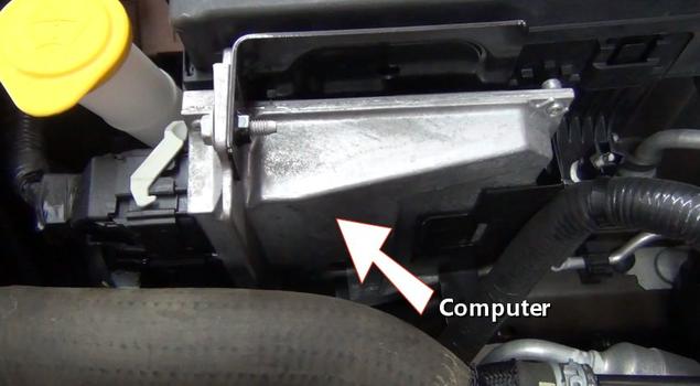
Step 6 - Once this data is received by the computer, an ignition coil trigger signal is generated by the coil drivers inside the computer. This signal timing is a product of manufacturer software loaded onto the computer which makes adjustments using feedback data from various sensors.

Computer
Step 7 - After the signal is generated its transferred to the ignition coil via the wring harness. Once the signal has been receive by the coil, a magnetic field collapses increasing from 12 volts to about 25,000 volts which is needed to bridge to gap of the spark plug.

Ignition Coils
Step 8 - An ignition coil is mounted over the spark plug directly. Some ignition designs are fitted with ignition wires which connects to the spark plugs.

Ignition Coil Removed
Step 9 - The ultimate goal of the ignition system is to fire the spark plug at the right time to maximize power and efficiency of the engines cylinders.

Spark Plug
Step 10 - Once the piston is near the top of its compression stroke the coil is triggered, releasing the voltage charge across the spark plug gap igniting the fuel air mixture inside the engine's cylinders. Some engine's utilize two spark plugs per cylinder to further enhance efficiency.

Spark Plug Ignition

Computer

Ignition Coils

Ignition Coil Removed
Step 9 - The ultimate goal of the ignition system is to fire the spark plug at the right time to maximize power and efficiency of the engines cylinders.

Spark Plug

Spark Plug Ignition
Comments
Post a Comment