No Tail Lights
Tail Light Test and Repair
Exterior running lights and tail lights out
Helpful Information
The running light circuit is controlled electrically through a BCM (body control module) or a LCM (lighting control module). These computer controllers are designed to warn about a bulb failure by illuminating a warning light on the dash. In older cars the headlight switch performed the actual power distribution to the headlights instead of using a relay and computer. American car's running lights are integrated into the blinker bulbs, while Japanese and European cars have separate lighting systems. Vehicles that have towing capabilities use a separate wiring system to power trailer lights, which are protected by additional fuses located in power distribution center. The rear license plate bulb is also illuminated when the running lights are on. Some systems are equipped with a timer that allows the lights to stay on for a predetermined amount of time after the driver has exited the vehicle.
Preferred Procedure: Replace bulbs with manufacturer replacement bulbs.
Common Problems
- Tail light bulbs are replaced with incorrect bulb causing improper operation.
- If tail lights stay on continuously, the headlight/tail light switch or BCM has failed.
Step by step guide on how to troubleshoot and repair automotive tail and running lights, this information pertains to not working, dim and flickering lighting systems.
Begin with the car on level ground, engine off with the parking brake set, wear protective gloves and eye wear. When performing tests avoid connecting power wires or terminals to ground (metal), fuse damage can occur, most automotive bulb testing procedures are done in this manner.
Difficulty Scale: 4 of 10
Step 1 - Identify the light or lights that are non operational. If one tail light bulb has failed, the problem is probably the bulb itself or a bad connection, if all lights are non-operational, follow down the guide to Step 5.
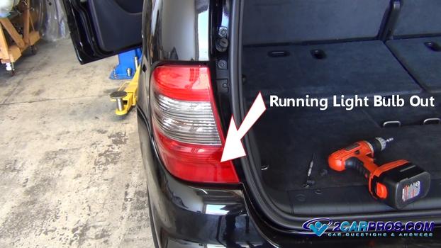
Running Light Bulb Out
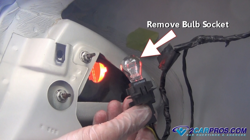
Step 2 - Remove bulb socket to expose the bulb for inspection, gently grasp the bulb and pull or push down and twist counterclockwise to remove, some bulbs are accessible by removing the lens itself while other require the removal of a plastic panel.
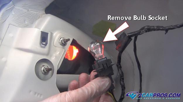
Removing Bulb Socket
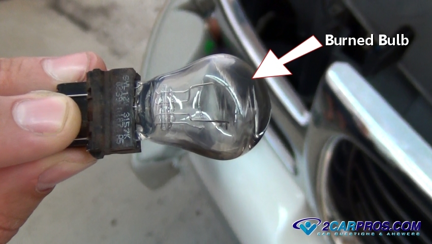
Step 3 - Remove the bulb and inspect, check for any burned color or white with blue smoke inside the bulb which is an indication of failure.

Burned Bulb
Step 4 - Replace the bulb with new and recheck before reinstallation.

Replacement Bulb
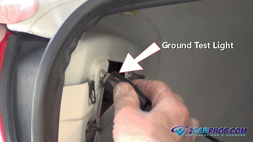
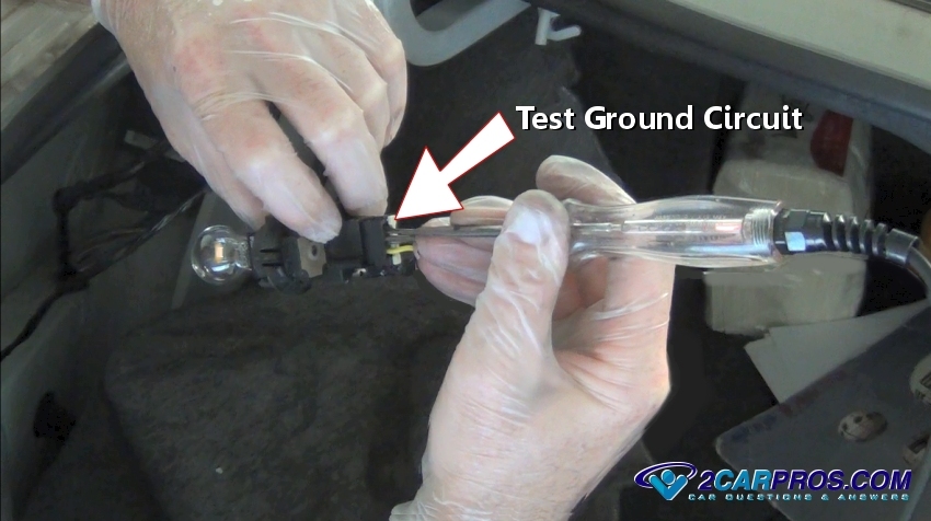
Step 5 - If a new bulb still doesn't operate, use a grounded testing light to help test power feeds to the bulb. Learn More

Ground Test Light
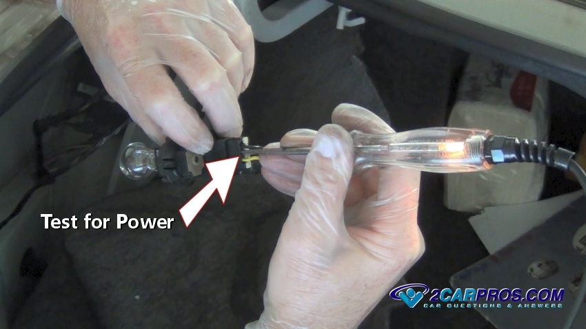
Step 6 - With the bulb removed (optional) and while the running lights are "ON", use a grounded test light to test the inner contacts of the bulb socket or wire connectors. Be careful not to touch the test light lead to the outer socket ring or to ground for this will cause a short circuit and fuse failure.

Testing For Power
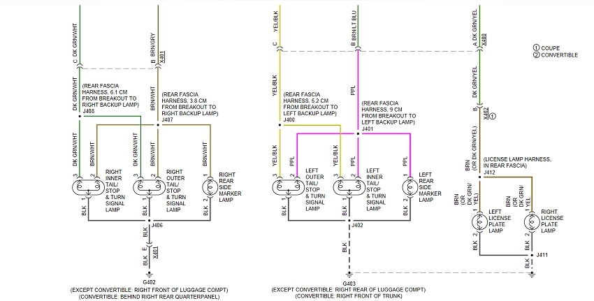
Step 7 - A diagram will facilitate repairs but is not needed for this test. Search Google images or an online service manual such as Mitchell1 to obtain a diagram.

Rear Lighting Wiring Diagram
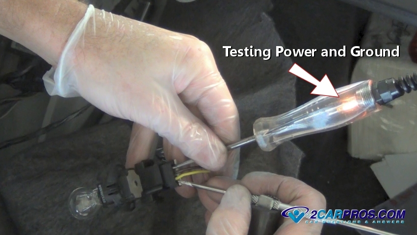
Step 8 - After confirming power is present at the socket, attach a pick or other pointy metal object to the test light clip, insert both probe and pick into the ground and power terminals or wiring, this test confirms power and ground at the socket.

Confirming Power and Ground Circuits
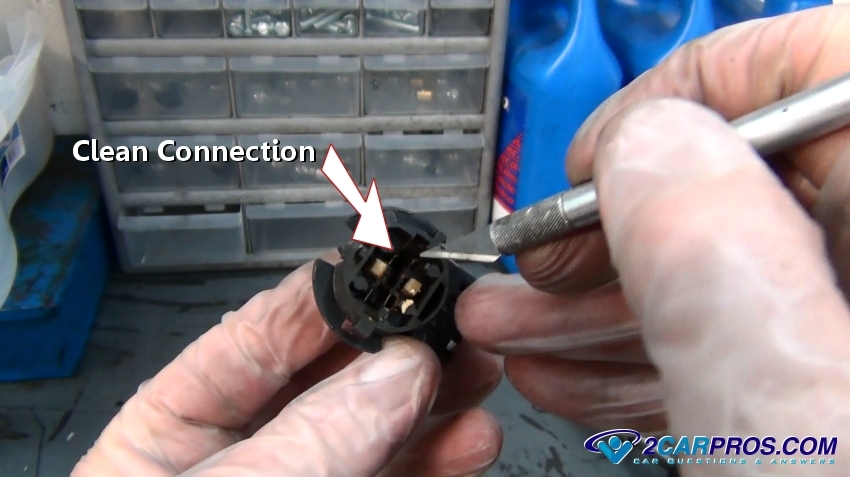
Step 9 - Using an Exacto blade or sandpaper, scrape clean the terminal connections that are inhibiting the electrical flow. Lighting sockets are subject to heat and can melt plastic and cause corrosion which promotes bulb operation failure, in severe cases the socket will need to be replaced.

Cleaning Socket Connections
Step 10 - If all running or tail lights are not working, a fuse is used to protect the lighting system from overload and short circuits, anytime more than one light bulb is out, the fuse is the first place to check, these fuses are located in the power distribution center (pdc). Learn More

Checking Fuses
Step 11 - A tail light control relay is used to help shoulder the electrical draw many bulbs can cause on a single circuit, this task is carried out by the BCM (body control module). The headlight/running light switch is used as the trigger circuit which sends a signal to activate the relay. When this relay fails, it will hinder the operation of the running lights. Learn More

Running Light Relay
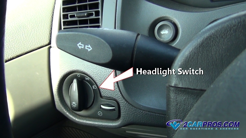
Step 12 - Next, remove the headlight switch to probe harness wires, the test light must be connected to positive power such as the battery which is needed to test ground circuit connections. Observe the test light while operating the switch, the light should follow the switch operation. On older cars, the switch controls headlight and tail light power, instead of grounding BCM triggers. For these systems use a grounded test light and test for twelve volts at the rear of the headlight switch connector (removed) on one or two of the terminals or wires. If no power is confirmed, repair the fuse holder or the power feed (maxifuse - fusible) from the fuse panel to the switch. If power is confirmed at the rear of the switch, turn the switch to the "ON" position and test the remaining terminals (or wires), power should be present at the remaining terminals. Learn More

Headlight Switch
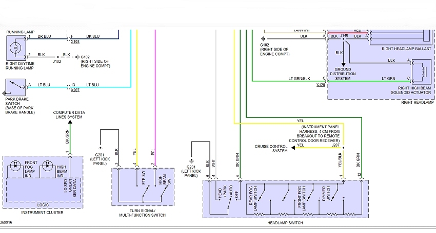
Step 13 - Diagram of a typical grounding BCM trigger system, each vehicle will vary. Wiring diagrams are obtainable at Google images or Mitchell1

Headlight Switch Wring Diagram
Step 14 - For final testing, a wiring diagram is needed to trace wires to be tested in the lighting circuit, with the switch in the "ON" position test for power output by probing lighting circuit wires which also tests the BCM operation.

Body Control Module Running Light Wiring Diagram
Step 15 - A dim light is caused by a poor ground circuit which causes the electrical flow to back feed resulting in higher than usual resistance. While the tail light bulb is installed, touch a grounded test light to the outer ring or ground wire of the bulb socket. If the bulb brightness increases, the bulb socket ground has gone open and must be cleaned or repaired-replaced.

Testing Dim Light Ground Circuit
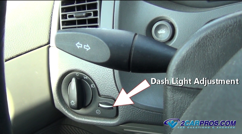
Step 16 - Dash lights are used in tandem with the running light system, these lights illuminate the instrument cluster at night while assisting visual aspects. The brightness of the dash lights can be adjusted by turning the rheostat near the headlight switch, if this adjustment is turned "OFF" the dash lights will not work. Some manufacturers have located the dash light illumination control remotely from the headlight switch, usually somewhere near the instrument cluster.

Dash Light Adjustment
Step 17 - Flickering or flashing lights occur because a power or ground source is being disconnected momentarily and then reconnected. Common causes for this condition is a loose fitting bulb inside the socket. To test for this condition expose the tail light bulb in question. Next, switch the tail lights on and move the bulb around slightly in the socket. If the bulb flickers tighten the socket or replace the bulb/socket to regain proper operation. If the complete system flickers (all bulbs flicker) wiggle the tail light fuse, relay and associated wiring at the headlight/tail light switch.
Step 18 - When a lighting system has been used for a period of time it can fail for a short time, and then regain operation once cooled which indicates the main connection inside the switch could be failing when it the contacts get hot. Heat is produced from amperage being drawn through a switch causing resistance. if this condition is occurring, the switch should be replaced.

Running Light Bulb Out
Removing Bulb Socket
Step 3 - Remove the bulb and inspect, check for any burned color or white with blue smoke inside the bulb which is an indication of failure.
Burned Bulb

Replacement Bulb
Ground Test Light
Testing For Power
Rear Lighting Wiring Diagram
Confirming Power and Ground Circuits
Cleaning Socket Connections

Checking Fuses

Running Light Relay
Headlight Switch
Headlight Switch Wring Diagram

Body Control Module Running Light Wiring Diagram
Testing Dim Light Ground Circuit
Dash Light Adjustment


Comments
Post a Comment