How to Test Car relay
Testing Car Relay
Car Electric Control unit Wiring And Relay Testing
Helpful Information
A relay is switch that utilizes an electrical trigger signal to activate. Once activated the relay connects an electrical supply to a particular accessory. These accessories can range from the main computer PCM (powertrian control module), radiator fan, fuel pump, door locks etc. There are two tests that should be considered when dealing with a relay problem, is the problem with the relay itself or is the problem a power or ground issue. A relay is prone to failure when used for a long periods of time (hot) or when the amperage of the accessory has increased beyond its designed use.
A rely should be considered as two separate halves, the primary side which utilizes an electromagnet to close the secondary electrical circuit. This electromagnet is activated by a simple power (+) and ground (-) much like a light bulb circuit. The second half of the relay is the "switch" that controls power to a particular accessory like a fuel pump or ignition system.
In short, when the primary side of the relay (electromagnet) is activated, it closes the contacts (switch) to supply power to operate the accessory.
Tools and Supplies Needed
Common Problems:
Tools and Supplies Needed
- Test light
- Small piece of automotive wire
- Small automotive bulb and socket
- When a relay warm up as in normal operation, the electrical contacts inside the relay can short circuit causing the electrical flow to stop, when the relay contacts cool it will resume the flow of electricity.
- When excessive amperage has been drawn through a relay circuit it can cause the relay contacts to "stick" not allowing the power to be shut off to the accessory. Example: When an ABS system motor ages it will draw excessive amperage causing the control relay to "stick". This condition will run down the battery until corrected.
- Moister can get inside a relay hindering the relay operation.
- When testing relay circuits for power, ground is accidentally contacted causing the fuse to fail.
Easy step by step procedure to test an automotive relay, this information pertains to all relay controlled circuits.
Difficulty Scale: 3 of 10
Step 1 - A relay is used to control (switch) a high amperage electrical circuit with a low amperage one, for example a radiator fan can pull up to 25 amps when in use, which would burn the computer circuit that controls it, a relay is used to bridge this circuit to prevent electrical damage.

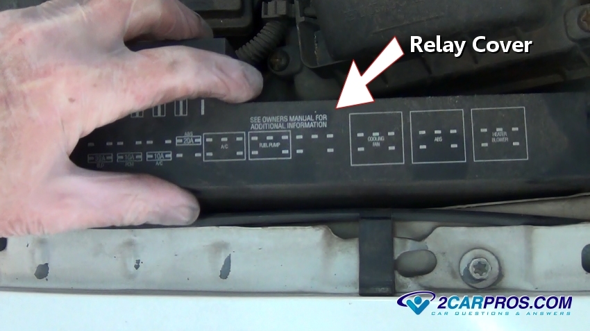
Power Distribution Center (PDC) - Relay Cover
Step 2 - Before beginning tests, use a test light and check all fuses and replace any that have failed. - Learn more

Testing Fuses
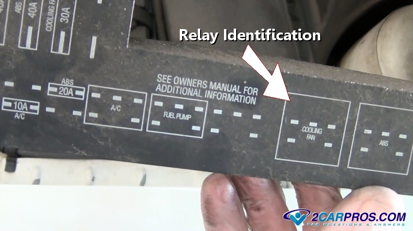
Step 3 - Many vehicles supply relay location and identification information on the lid of the PDC. If this information is not available, check the owners manual or Google Images

Relay Identification
Step 4 - Once the relay has been identified, gently grasp or touch the relay in question, have a helper turn the ignition key to the on position, then crank the engine over, the relay should click in one of the ignition switch positions. If so the trigger circuit of the relay electrical system is working, if not continue to next step. ( Note: If the relay clicks and the circuit is still not working there is a good chance the contacts inside the relay have shorted.)
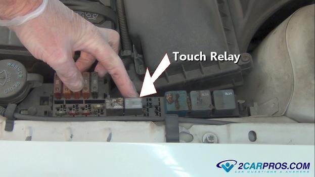
Feel Relay Action
Step 5 - Next, remove the relay for inspection, grasp the relay and pull outward while slightly wiggling the relay housing, note the orientation of the relay, it must be installed the correct direction.

Removing Electrical Relay
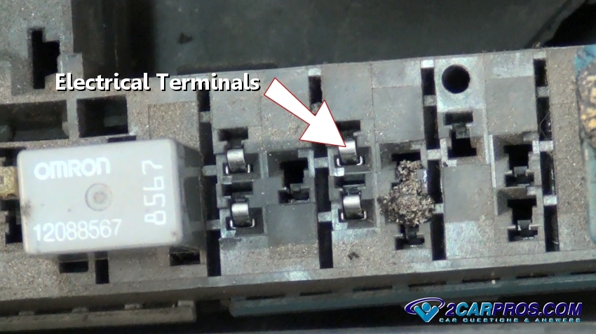
Step 6 - Once the relay has been removed, inspect the relay terminals for signs of extreme heat or corrosion.

Inspecting Relay Terminals
Step 7 - The relay is mounted in four electrical terminals housed in plastic and when overheated (due to overload or resistance caused by a poor connection) can distort and melt.
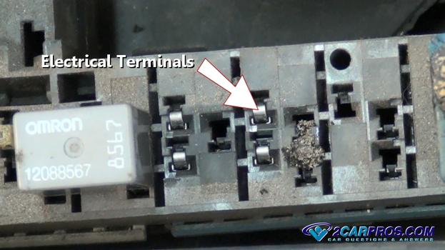
Inspect Electrical Terminals
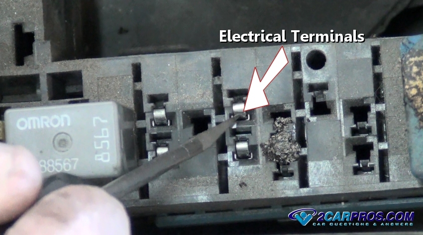
Step 8 - Use as small metal scribe or tool to scrape clean any corrosion to ensure a good connection once the new relay is installed.
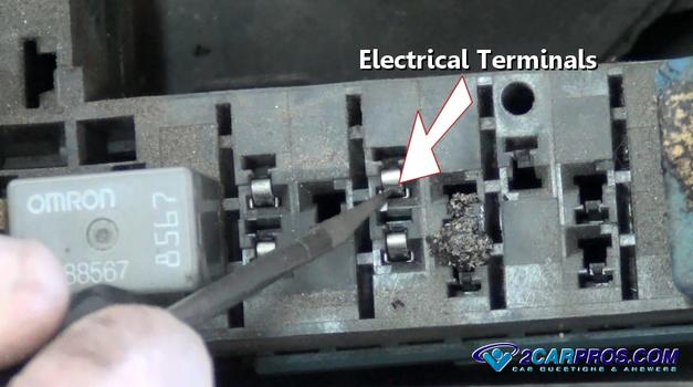
Clean Electrical Terminals
Step 9 - Most relay's describe the internal circuit by an illustration on the side of the relay.
Relay Terminal Identification
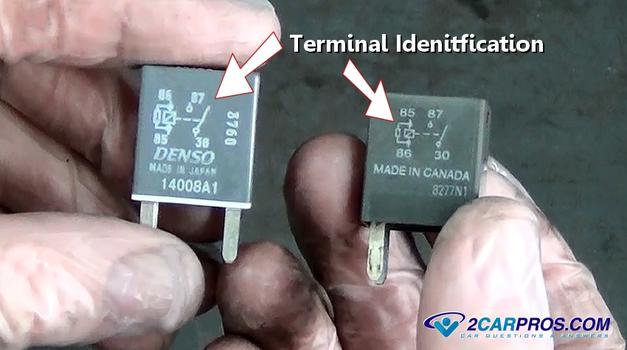
Relay Terminal Identification
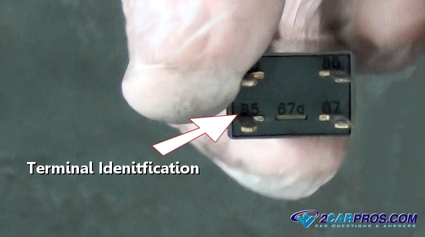
Step 10 - Each terminal is identified at the relay base.
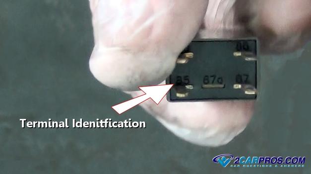
Relay Terminal Identification Base
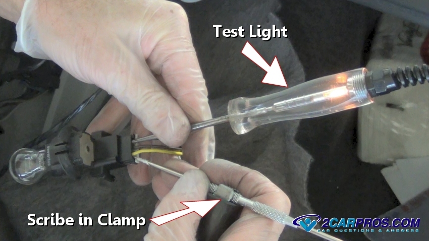
Step 11 - To test the trigger or primary side of the relay set up a test light by connecting a scribe to a test light clamp, being illustrated in the picture below while testing the tail light socket.
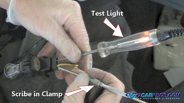
Scribe in Test Light Clamp
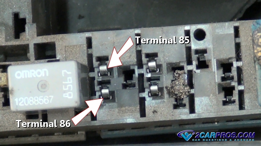
Step 12 - Once the test light is set up connect each end to terminals 86 and 85. Now start the vehicle and operate the accessory switch, the test light should illuminate, if not the switch or circuit ground has shorted. ( Note: if the circuit is computer controlled a delay could be programmed into the operation of the accessory, additionally if a cooling fan is being tested the engine must reach operating temperature before the computer will trigger the circuit.) Use the test light grounded to check for power, and then switch the test light lead to the power side of the battery to check for circuit ground.
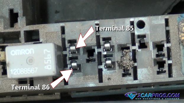
Testing Circuit 86 and 85
Step 13 - Next, use a piece of wire automotive wire (20 to 16 gauge) and strip both ends exposing the copper wire. Turn the ignition to the "ON" position and jump terminals 87 and 30 the relay is now jumped and the accessory should activate, if so the relay has failed. If no power is observed at either 87 or 30, the fusible link or maxi fuse has shorted. Example: Testing the radiator cooling fan relay, the cooling fan should be operating.
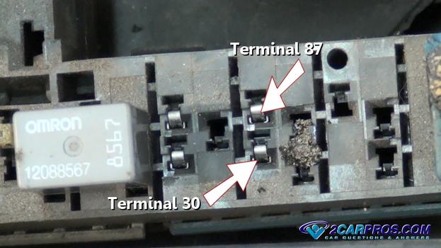
Testing Circuit 87 and 30
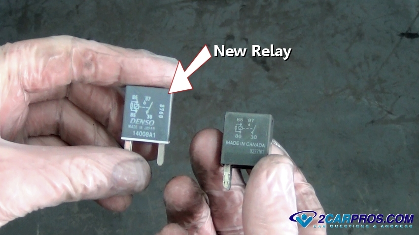
Step 14 - When replacing a relay be sure to match up the terminal location from the old relay to to the new unit.

New Relay
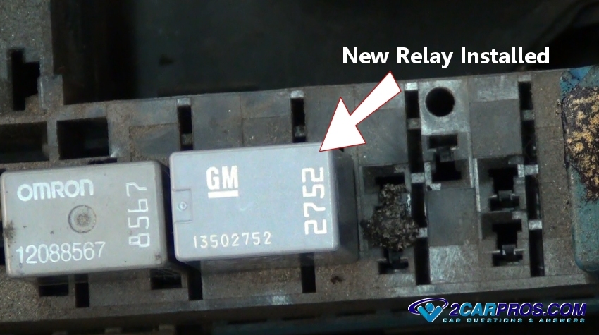
Step 15 - When installing the new relay be sure the orientation is correct or the relay will not work.

New Relay Installed
Step 16 - Once proper relay operation has resumed, reinstall the relay (PDC) cover.

Reinstall Relay Cover
Additional Testing
When a particular two wire accessory is not operating, use a grounded test light to check for power at the wiring harness (either wire). If there is no power, the electrical system must be tested starting with the fuse then the relay. If power is present use the test light connected to battery power to check the ground circuit. if these tests check out, the accessory is bad and needs to be replaced.
Some relay's can differ from this configuration but follow the same principle. To confirm the wiring configuration consult a wiring diagram from Google Images or aservice manual.
Intermitted Failure
Step 1 - To test for intermitted relay failures which are common, remove the relay in question, take a small wire strand, about two inches long and insert it into the relay connector terminal 87 or 30.
Step 2 - Next, reinstall the relay while keeping the wire strand inserted and clear of any other terminals or metal (ground).
Step 3 - With the wire strand secured in the relay terminal, attach the wire to a small automotive bulb and socket and ground. ( Note: A side marker bulb and socket work great because of its small size, make the wires long enough so the bulb can be seen while driving.)
Step 4 - Temporarily mount the small bulb in a visible area to be seen while driving, masking taped to the hood or dash works well.
Step 5 - This test can be used to test all aspects of the wiring circuitry by moving the bulb ground to power. The bulb will now illuminate when the relay is use, and will go out to signal a failure.
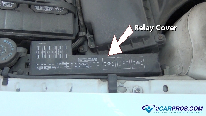
Power Distribution Center (PDC) - Relay Cover
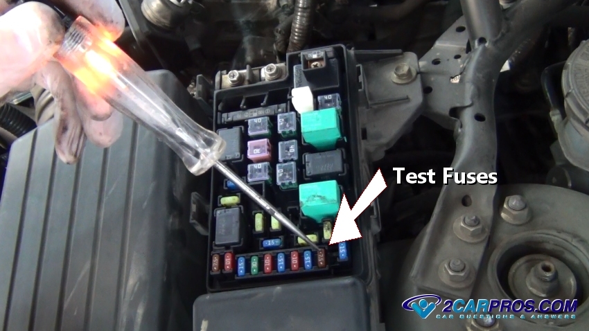
Testing Fuses
Step 3 - Many vehicles supply relay location and identification information on the lid of the PDC. If this information is not available, check the owners manual or Google Images
Relay Identification

Feel Relay Action
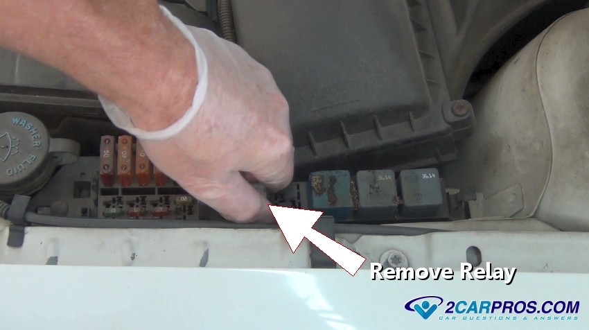
Removing Electrical Relay

Inspecting Relay Terminals
Inspect Electrical Terminals
Clean Electrical Terminals
- Terminals 86 and 85 are the primary side of the relay, which utilizes an electromagnet to close (connect) the secondary electrical circuit inside the relay. This electromagnet is activated by a simple power (+) and ground (-) much like a light bulb circuit.
- Terminals 87 and 30 are the secondary side of the relay which acts as the "switch" that connects electrical current from one terminal to the other.
- Terminal 87a is not widely used and does not need to be connected for the relay to operate. 87a can be used for many different things such as relay activation monitoring or connecting a separate circuit that uses power when the relay is not in use.

Relay Terminal Identification
Relay Terminal Identification Base
Scribe in Test Light Clamp
Testing Circuit 86 and 85

Testing Circuit 87 and 30
New Relay
New Relay Installed
Reinstall Relay Cover
Additional Testing
Intermitted Failure


Comments
Post a Comment