How To Replace ABS Wheel Speed Sensor
ABS Wheel Speed Sensor Replacement Guide
Customers Facing Problems With ABS Wheel Speed Sensors Also Asked Such Questions
How To Replace ABS Wheel Speed Sensor
front wheel speed sensor
front wheel sensor problem
abs wheel speed sensor symptoms
passive wheel speed sensors
abs speed sensor problems
front wheel sensors abs system
wheel speed sensor air gap spec
abs wheel speed sensor how it works
There are many things that can cause your ABS light to come on. Some are serious, so you should never just ignore the light. But there are times when the light comes on, but can be met with a simple solution. For instance, a dirty ABS wheel sensor can cause the system to trigger the ABS light during your ABS computer's self evaluation cycle. You'll be shocked when you see how much road gunk can accumulate on this very important sensor.
ABS Sensor
This sensor is also used in some traction control systems, so if you've got a traction control, or anti-skid warning illuminated you might find that cleaning the ABS sensors will remedy this, as well.
Even if your ABS light hasn't made an appearance, it's a good idea to clean the sensors. A good time to do it would be during brake pad replacement when you have the wheels off anyway. At this point it's a 10-minute job rather than an hour or two.
mounted at each wheel that monitors wheel speed. When the sensor "sees" that the wheel locks up during hard braking, the sensor automatically releases brake pressure momentarily and begins pumping the brakes for you at a very rapid pace. The pumping action of the ABS system is much faster than what you would ever be able to do manually and allows you to better control the vehicle during hard braking. When these sensors fail, your ABS system will no longer work until you replace the faulty sensor. Replacement sensors can be purchased from most auto parts stores.
An ABS wheel speed sensor is used to send feedback reference voltage to the system's computer which controls the system. Your vehicles ABS brake system relies on these speed sensors which connect to an electronic module while using a fluid pump motor to activate the system.
Electronic sensors are located at all four wheels to monitor the rotation speed of each tire. This monitoring is performed to help the main controller differentiate brake system pressure to each wheel when the brake system is abruptly applied.
By doing this the wheel that is rotating at a lesser speed than the remaining wheels will experience a brake fluid pressure drop to help allow the wheel to start rotating at the same rate as the remaining wheels.
These sensors are prone to failure and will usually illuminate a red or yellow brake system warning light when there is trouble with one or more of them. To determine if a sensor has failed there are one of two methods that can be used.
The first method is to attach an expensive system scan tool to retrieve the trouble codes, once the code is discovered finding the definition is next step which will pinpoint the particular bad sensor.
If no scanner is available an alternative method can be used. Remove the electrical connector from each wheel sensor and by using a hand held multi-meter test the voltage produced while rotating the wheel, if no voltage is produced the sensor is bad.
SEE ALSO: TESTING AN ABS WHEEL SENSORS These sensors are not to difficult to repair and will take about an hour and cost between $25 and $140 depending if the sensor is separate from the hub or not, find the sensor your need on Amazon, dealer or the local parts store. Please follow this guide I have created for you to repair your own sensor.
Some sensors can be removed separately while others are integrated into the wheel bearing assembly which is what I have shown here.
Open the hood and loosen the retaining nut on the cable clamp connected to the negative battery terminal. Then slide the clamp off the negative battery terminal to cut power to all of the ABS sensors.
Turn the wheel lug nuts counter-clockwise with a tire wrench 1/4 turn. Do not unseat the wheel from the wheel hub, however. You only need to break the lug nuts loose so that it is easier to remove the wheel once it is up off the ground.
Raise the vehicle onto jack stands. Lift up on the front jack point of the vehicle located behind the radiator using a floor jack. The jack point will normally be the front cross-member or an extension of the frame of the vehicle used specifically as a jack point. Place jack stands underneath the front pinch welds of the vehicle, located underneath the driver and passenger side doors, and lower the vehicle onto the jack stands.
Finish removing the wheel lug nuts and pull the wheel off the wheel hub assembly.
Locate the ABS sensor on the wheel hub assembly. Normally, this will look like a small black box mounted to the wheel hub.
Unplug the electrical wiring from the ABS sensor.
Remove the screws or bolts that hold your ABS sensor in place and pull the sensor off the hub with a screwdriver or socket wrench.
Align the mounting holes on the new sensor with the mounting holes on the wheel hub for the new ABS sensor.
Thread and tighten the bolts or screws.
Plug the electrical connector back into the ABS sensor.
Mount the wheel and tighten the lug nuts with a tire wrench.
Lower the vehicle to the ground and tighten the wheel lug nuts to between 75 and 100 foot-pounds, depending on the vehicle's wheel lug nut torque specifications, using a torque wrench.
TOOLS AND SUPPLIES NEEDED TO COMPLETE THE REPAIR
- Replacement wheel speed sensor
- Tool set
- Shop towels
- Protective eye wear
- Work gloves
- Floor jack
- Jack stands
STEP 1
Remove the wheel cover if needed and break the lug nuts loose one or two turns using a lug wrench supplied with the spare tire. Once completed use a floor jack under the frame or control arm to lift the vehicle, once raised use a jack stand under the frame for safety. After you have finish removing the lug nuts, remove the tire. Slide the tire under the vehicle for an additional measure of safety.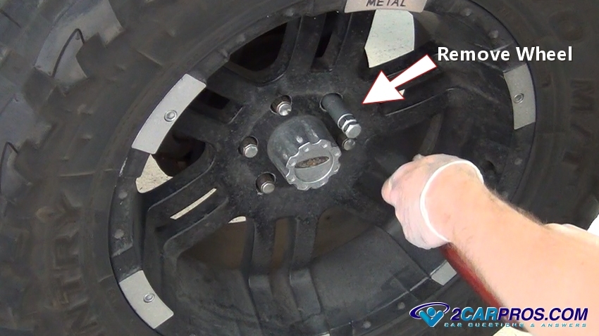
STEP 2
Once the tire has been removed, locate and remove the brake caliper mounting bolts to remove the caliper. After the bolts have been remove, grasp the caliper and rock it back and forth slightly to loosen and remove. Then place the caliper in a secure spot, do not allow it to hang by the brake hose, this can damage the hose and cause a safety issue.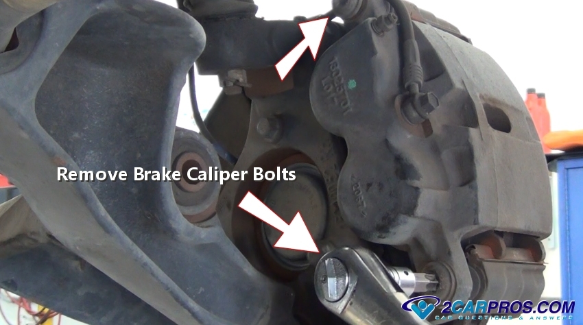
STEP 3
Loosen and remove the brake caliper mounting bracket bolts to remove the bracket. These can be fairly tight so get a good grip on the wrench or socket being used. Be sure to hold the bracket because once the bolts are removed it can fall causing damage to the part and possibly hurt you as it falls.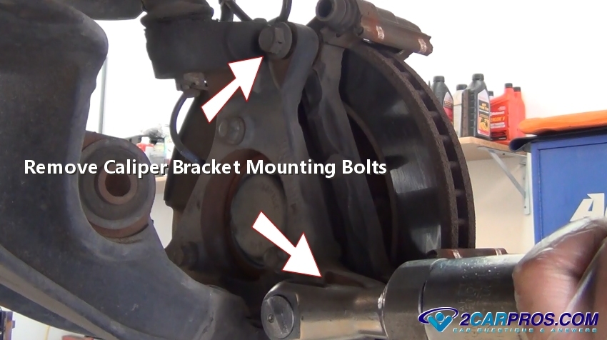
STEP 4
With the caliper mounting bracket out of the way it's time to remove the brake rotor, if the rotor is stuck on the hub use a hammer to "shock" the rotor loose by striking it on the flat surface of the rotor and against the bearing hub or axle (The rotor can be tight due to rust and the press of the lug nuts while holding the tire on).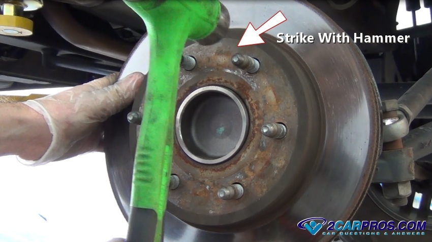
STEP 5
After the rotor has been removed, it will expose the sensor which can be replaced separately on some models, or along with the bearing hub. Some sensors are simply bolted to the rear of the spindle or backing plate on the rear of the car, in which case the removal of the brake assembly is not needed. Be sure to inspect which kind of sensor configuration you have before beginning the job.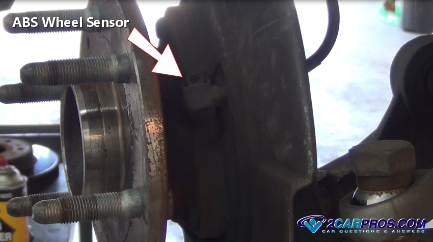
STEP 6
Use a socket or wrench to remove the sensor mounting bolt which can be Allen, hex or torx head bolts. After the mounting bolt has been removed, grasp the sensor to remove it from the bearing hub or spindle. While the sensor has been removed inspect the sensor stator ring by rotating the hub to confirm there is no damage existing to the ring. If the ring shows signs or wear or missing teeth replacement is required and could be the cause of the warning light.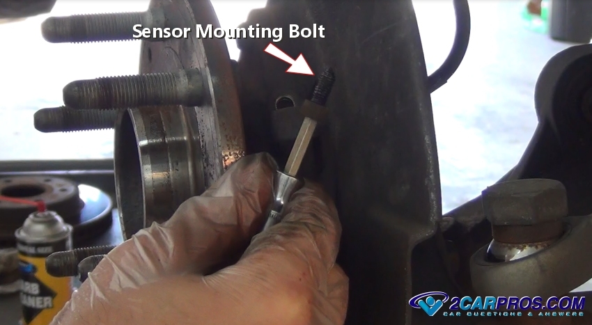
STEP 7
Locate the sensor wiring connector which is usually near the frame or upper control arm. Release the safety clasp and gently remove the connector from the wiring harness. Match the new sensor to the old unit to ensure proper installing and operation, confirm the electrical connector is clean from dirt and grease before reassembly.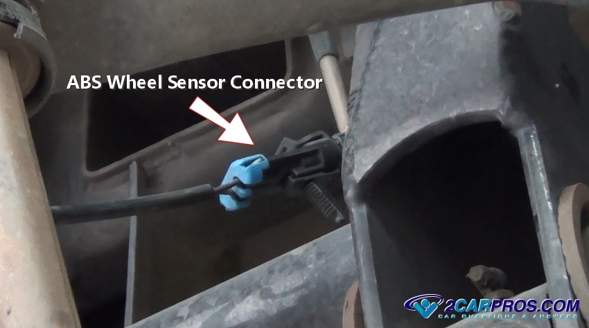
What is an ABS sensor and where is it located?
In today’s automotive world, anti-lock brakes have become standard components in vehicles and are an extremely important safety feature. When driving on a slippery road and firmly engaging your brakes, your vehicle’s wheels could potentially lock up, causing the vehicle to skid or spin uncontrollably from the loss of traction. This is obviously not ideal as far as safety goes. The main purpose of the anti-lock braking system (ABS) is to prevent a vehicle’s wheels from locking up at a time when momentary wheel rotation is actually needed. By allowing the wheels to maintain their traction with the road surface, the anti-lock braking system is able to stop the vehicle faster, and allow the driver to steer away from potential hazards. The anti-lock braking system consists of several components, one of which is the ABS sensor.
The ABS sensor, also commonly referred to as a wheel speed sensor, ABS speed sensor, ABS brake sensor, or ABS wheel speed sensor, is part of the anti-lock brake system and is used to measure the amount of times a wheel rotates (i.e. its speed). This information is used by the system to determine if a wheel is slipping more than the others and if the brakes need to be engaged in an emergency. In a lot of newer models, your ABS speed sensors can also be part of electronic traction control systems and even stability control systems in some trucks and SUVs. In terms of location, older designs use an external brake sensor near the wheel in conjunction with a ring gear located either on the axle or the back of the brake rotor, while newer versions incorporate these pieces into the wheel hub and bearing assembly.
A vehicle can have up to four wheel speed sensors. Some vehicles have two sensors: one on the left and right wheel in the front or rear of the vehicle. Others will have three wheel speed sensors, with a shared one located in the rear axle in addition to one on the left and right wheel in the front of the vehicle. Lastly, some vehicles will have four ABS sensors, one on the left and right wheel in both the front and rear of the vehicle. The number of ABS sensors that a car or truck will have depends on the type of brakes that the vehicle has.
How do I know if my wheel speed sensor needs to be replaced?
The most common reasons for replacing a wheel speed sensor are damage or contamination. Since the sensor is close to the ground, road debris can cut or fray the wiring. If not held securely in place, the harness may chafe on nearby chassis parts. Since the brake sensor is electrical, exposure to the elements (such as ice and moisture) can cause connectors to corrode or internals parts to short out. A defective or malfunctioning ABS speed sensor will typically set an ABS light on your instrument panel, and trigger an ABS diagnostic code in your vehicles computer. It also may throw a traction control light on as well.
Can I replace an ABS speed sensor myself?
Replacing the ABS speed sensor varies depending on the vehicle. For vehicles that have the external style sensor, replacement is as simple as unplugging the connector from the vehicle harness and unbolting the sensor from its location. On vehicles that have the ABS brake sensor integrated into the wheel hub and bearing assembly, the job is more involved since the entire assembly will have to be removed, requiring at least the brakes to be taken out of the way.
2004 GMC CANYON WHEEL SPEED SENSOR REPLACEMENT
Wheel Speed Sensors
Removal & Installation
2-Wheel Drive
CAUTION
Avoid taking the following actions when you service wheel brake parts:
Do not grind brake linings
Do not sand brake linings
Do not clean wheel brake parts with a dry brush or with compressed air Some models or aftermarket brake parts may contain asbestos fibers which can become airborne in dust. Breathing dust with asbestos fibers may cause serious bodily harm. Use a water-dampened cloth in order to remove any dust on brake parts. Equipment is available commercially in order to perform this washing function. These wet methods prevent fibers from becoming airborne.
Before servicing the vehicle, refer to the Precautions Section.
Raise and support the vehicle.
Remove the wheel and tire.
Remove the brake caliper bracket bolts.
NOTE
Support the brake caliper with heavy mechanic wire, or equivalent, whenever it is separated from its mount and the hydraulic flexible brake hose is still connected. Failure to support the caliper in this manner will cause the flexible brake hose to bear the weight of the caliper, which may cause damage to the brake hose and in turn may cause a brake fluid leak.
Without disconnecting the brake hose, remove the brake caliper and bracket as an assembly and support with heavy mechanics wire or equivalent.
NOTE
Note the location of the retainers for the wheel speed sensor to the upper control arm and the body to aid installation and ensure correct harness routing.
Release the retainers securing the wheel speed sensor wiring harness to the upper control arm.
Disconnect the wheel speed sensor electrical connector.
Remove the speed sensor electrical connector from the body.
NOTE
Note the orientation of the wheel speed sensor harness to the steering knuckle to ensure correct installation.
Using white or bright colored paint, mark the location of the speed sensor wiring harness to the steering knuckle.
Remove the wheel speed sensor harness bracket bolt.
Remove the wheel hub/bearing bolts.
Remove the brake rotor and the wheel hub/bearing as an assembly while routing the wheel speed sensor harness through the steering knuckle.
Using white or bright colored paint, mark the location of the wheel speed sensor harness to the wheel hub/bearing assembly.
NOTE
Do not lever or pry against the wheel speed sensor tone wheel under the wheel speed sensor. Lever against the wheel hub only.
Using a suitable tool, pry or lever the wheel speed sensor off of the wheel hub/bearing housing. Discard the wheel speed sensor.
To install:
NOTE
Align the wheel speed sensor harness with the reference mark on the wheel hub/bearing assembly.
Position the wheel speed sensor on the wheel hub/bearing assembly.
Carefully press the wheel speed sensor squarely onto the wheel hub/bearing assembly until fully seated against the lip of the wheel hub/bearing assembly housing.
NOTE
Align the wheel speed sensor harness with the reference mark on the steering knuckle.
Install the wheel hub/bearing and brake rotor assembly to the steering knuckle.
NOTE
Use the correct fastener in the correct location. Replacement fasteners must be the correct part number for that application. Fasteners requiring replacement or fasteners requiring the use of thread locking compound or sealant are identified in the service procedure. Do not use paints, lubricants, or corrosion inhibitors on fasteners or fastener joint surfaces unless specified. These coatings affect fastener torque and joint clamping force and may damage the fastener. Use the correct tightening sequence and specifications when installing fasteners in order to avoid damage to parts and systems.
Install the wheel hub/bearing bolts. Tighten the bolts to 92 ft. lbs. (125 Nm).
Install the wheel speed sensor harness bracket bolt. Tighten the bolt to 14 ft lbs. (20 Nm).
Install the wheel speed sensor harness retaining clips to the upper control arm.
Install the wheel speed sensor harness connector to the body. Connect the wheel speed sensor harness electrical connector.
Install the brake caliper and bracket assembly to the steering knuckle.
Install the brake caliper bracket bolts. Tighten the bolts to 129 ft. lbs. (175 Nm).
Install the tire and wheel.
Lower the vehicle.
4-Wheel Drive
CAUTION
Avoid taking the following actions when you service wheel brake parts:
Do not grind brake linings
Do not sand brake linings
Do not clean wheel brake parts with a dry brush or with compressed air Some models or aftermarket brake parts may contain asbestos fibers which can become airborne in dust. Breathing dust with asbestos fibers may cause serious bodily harm. Use a water-dampened cloth in order to remove any dust on brake parts. Equipment is available commercially in order to perform this washing function. These wet methods prevent fibers from becoming airborne.
Remove the steering knuckle.
Remove the wheel speed sensor harness bracket bolt from the steering knuckle.
NOTE
Note the orientation of the wheel speed sensor harness to the steering knuckle to ensure correct installation.
Using white or bright colored paint, mark the location of the wheel speed sensor harness to the steering knuckle.
Remove the wheel hub/bearing bolts.
Remove the brake rotor and the wheel hub/bearing as an assembly from the steering knuckle while routing the wheel speed sensor harness through the steering knuckle.
Using white or bright colored paint, mark the location of the wheel speed sensor harness to the wheel hub/bearing assembly.
NOTE
Do not lever or pry against the wheel speed sensor tone wheel under the wheel speed sensor. Lever against the wheel hub only.
Using a suitable tool, pry or lever the wheel speed sensor off of the wheel hub/bearing housing. Discard the wheel speed sensor.
To install:
NOTE
Align the wheel speed sensor harness with the reference mark on the wheel hub/bearing assembly.
Position the wheel speed sensor on the wheel hub/bearing assembly.
Carefully press the wheel speed sensor squarely onto the wheel hub/bearing assembly until fully seated against the lip of the wheel hub/bearing assembly housing.
NOTE
Use the correct fastener in the correct location. Replacement fasteners must be the correct part number for that application. Fasteners requiring replacement or fasteners requiring the use of thread locking compound or sealant are identified in the service procedure. Do not use paints, lubricants, or corrosion inhibitors on fasteners or fastener joint surfaces unless specified. These coatings affect fastener torque and joint clamping force and may damage the fastener. Use the correct tightening sequence and specifications when installing fasteners in order to avoid damage to parts and systems.
NOTE
Align the wheel speed sensor harness with the reference mark on the steering knuckle.
Install the brake rotor and wheel hub/bearing assembly to the steering knuckle.
Install the wheel hub/bearing bolts. Tighten the bolts to 92 ft. lbs. (125 Nm).
Install the wheel speed sensor harness bracket bolt to the steering knuckle. Tighten the bolt to 14 ft. lbs. (20 Nm).
Install the steering knuckle assembly.
Bleeding the Brake System
When bleeding the brake system, bleed one brake cylinder at a time, beginning at the cylinder with the longest hydraulic line (farthest from the master cylinder) first. ALWAYS Keep the master cylinder reservoir filled with brake fluid during the bleeding operation. Never use brake fluid that has been drained from the hydraulic system, no matter how clean it is.
The primary and secondary hydraulic brake systems are separate and are bled independently. During the bleeding operation, do not allow the reservoir to run dry. Keep the master cylinder reservoir filled with brake fluid.
Clean all dirt from around the master cylinder fill cap, remove the cap and fill the master cylinder with brake fluid until the level is within 1 / 4 in. (6mm) of the top edge of the reservoir.
Clean the bleeder screws at all 4 wheels. The bleeder screws are located on the back of the brake backing plate (drum brakes) and on the top of the brake calipers (disc brakes).
Attach a length of rubber hose over the bleeder screw and place the other end of the hose in a glass jar, submerged in brake fluid.
Open the bleeder screw 1 / 2 - 3 / 4 turn. Have an assistant slowly depress the brake pedal.
Close the bleeder screw and tell your assistant to allow the brake pedal to return slowly. Continue this process to purge all air from the system.
When bubbles cease to appear at the end of the bleeder hose, close the bleeder screw and remove the hose.
Check the master cylinder fluid level and add fluid accordingly. Do this after bleeding each wheel.
WARNING
Clean, high quality brake fluid is essential to the safe and proper operation of the brake system. You should always buy the highest quality brake fluid that is available. If the brake fluid becomes contaminated, drain and flush the system, then refill the master cylinder with new fluid. Never reuse any brake fluid. Any brake fluid that is removed from the system should be discarded. Also, do not allow any brake fluid to come in contact with a painted surface; it will damage the paint.
Repeat the bleeding operation at the remaining 3 wheels, ending with the one closet to the master cylinder.
Fill the master cylinder reservoir to the proper level.
CAUSES OF FALSE ABS WARNINGS: NON-ABS PROBLEMS TRIGGER FAULT CODES, ANTILOCK DASH LIGHTS
A multitude of problems can trigger erroneous fault codes on antilock brake systems (ABS), service experts said. Many codes are spurred by wheel-speed sensor problems because these sensors are the most vulnerable, highest-wear components in the entire ABS system. However, common problems in the fundamental brake system also trigger many ABS codes. All brake service sources agreed that the ABS system is only as good as the basic brake system to which it's connected. When the ABS control computer sets a fault code, it disables the ABS system and the conventional brake system continues operating. The computer also turns on the antilock warning light on the dashboard.
Speed sensor snafus
Sources said that speed-sensor-related quirks often turn on the antilock warning light. For example, erratic, uneven traction on snowy or icy roads may vary wheel-speed and/or spur extended ABS operation, turning on the warning light.
When technicians can find nothing obviously wrong and suspect snow or ice tricked the ABS computer into disabling the system, they should follow the prescribed procedure for clearing the computer's memory. Then road test the vehicle and see if the trouble code and illuminated warning light return, said Joe Meyer, an instructor at Professional Automotive Career Training (PACT), a division of Conrad's Goodyear, Cleveland.
Service managers TIRE BUSINESS interviewed agreed the severe ice and snow conditions that prevailed in much of the country last winter turned on many antilock warning lights.
At Kieser's Tire & Service Center, Fairless Hills, Pa., service manager Timothy Steigerwalt encouraged technicians to resist the temptation to leap into detailed ABS diagnostics when the initial inspection shows nothing wrong with the system or the vehicle.
Writing down codes, clearing the computer memory and road testing to see if the codes recur is a successful technique for diagnosing engine control systems. But it's equally practical for ABS troubleshooting, he said.
Plus, understanding subtle factors such as the impact of road conditions on ABS operation is part of the practical outlook needed to diagnose the systems accurately, he added.
Although visual inspections reveal many root causes of ABS trouble, technicians may not automatically associate the problems they find with ABS. That's why it's critical to ask the customer if anyone has worked on his vehicle recently. Learning what was done to the vehicle may be the mental bridge that links the tech's findings with the root of the ABS problem, noted Ron Bulla, operations and training manager at Kieser's.
For instance, a car that had been aligned recently at another shop came in with the antilock warning light on and a fault code indicating an erratic front-wheel speed sensor. Visual inspection showed the cam bolt for adjusting camber on that side of the vehicle was extremely loose. The technician torqued the bolt to specification in the interest of safety-and fixed the ABS problem at the same time.
Further investigation confirmed the loose bolt caused the sensor to vibrate violently, causing an erratic wheel-speed signal and triggering a fault code, Mr. Bulla explained.
Likewise, some vehicles come into a shop needing nothing more than routine brake service and leave with an ABS problem. Technicians who are careless with wrenches, hammers, drums and rotors often whack wheel-speed sensors, damaging the sensor or altering its air gap, said Tod Lange, an instructor and field service specialist with Raybestos/Brake Parts Inc.
As explained in earlier service supplements (March 23, 1992 and August 9, 1993), ABS wheel-speed sensors are magnetic-impulse sensors that produce an AC voltage signal. The air gap between the stationary permanent magnet and the rotating reluctor ring is critical to producing a consistent, accurate speed signal.
Mr. Lange said that besides being high-failure components, wheel-speed sensors often become contaminated with fine metal particles. The problem causes erratic wheel-speed signals that confuse the
ABS computer, causing it to disable the system, store a trouble code and turn on the antilock warning light.
Brake service experts at EIS Brake Parts and Brake-Pro Systems both confirmed that metal particle contamination can set false fault codes. It can also cause phantom symptoms such as an antilock warning light flickering on and off for no apparent reason, they said.
The wheel-speed sensor on many popular light trucks is mounted in the side of the transmission or rear differential housing. The inner tip of the permanent-magnet sensor is exposed to transmission or differential oil because it monitors the speed of the transmission output shaft or differential ring gear.
Consequently, metal chips caused by normal drivetrain wear accumulate on the sensor tip over a long period of time.
Mr. Lange urged techs to remove the wheel-speed sensor from the transmission or differential, clean it and retest the vehicle before proceeding with ABS diagnosis. Also, change the transmission or differential oil. It also pays to open up the differential on a high-mileage vehicle and carefully wipe out the bottom of the differential housing.
Brake-Pro Systems technicians said the presence of permanent-magnet speed sensors underscores the importance of washing all drums and rotors after cutting these parts on a lathe. Besides contributing to rough brake application and brake noises, the metal dust may be drawn to the speed sensor.
Plus, grease thrown from a leaking CV boot may soil an ABS speed sensor or reluctor ring. Grease on a reluctor ring may attract metal dust from a rotor or semi-metallic brake lining. A metal-laden grease spot may trigger a speed sensor code because the computer thinks the spot is an extra tooth on the reluctor ring, EIS technicians said.
Some sources said that when in doubt, technicians should wash off a suspect wheel-speed sensor with an appropriate brake or electrical cleaner, then retest the vehicle.
The harmless-looking, fine black brake dust on the sensor could contain enough fine metal particles to disturb the wheel-speed signal.
At PACT, Mr. Meyer said experience confirms that running a space-saver spare tire on an ABS-equipped car may turn on the antilock warning light and set a wheel-speed code.
After reinstalling the standard-size tire, technicians need only clear the ABS computer memory and drive the vehicle.
Diagnosing Antilock Brake System Wheel Speed Sensors
When a wheel speed sensor (WSS) fails or there's a problem in the sensor's wiring circuit, it usually disables the ABS system and causes the ABS warning light to come on. Loss of a wheel speed signal is a serious problem because the ABS module needs accurate input from all its sensors to determine whether or not a wheel is locking up. Without this vital information, the ABS system can't do its thing.
Wheel speed sensors produce an alternating current (AC) output voltage that varies in frequency and amplitude with wheel speed. The faster the wheel turns, the greater the frequency and amplitude of the sensor's output signal. The strength of the signal can be affected by resistance in the sensor, resistance in the wiring and connectors, metallic debris on the end of the sensor, and the air gap between the sensor and tone ring mounted on the axle, hub, brake rotor, drum or CV joint.
A narrow air gap is usually necessary to induce a strong signal in the sensor's magnetic windings. Air gaps typically range from .016 in. to as much as .050 in. (0.40 to 1.3 mm) depending on the application. If the ABS warning light is on and you find a code for a wheel speed sensor (and the sensor is adjustable), the problem may be nothing more than too wide an air gap. Use a brass or nonmagnetic feeler gauge set the gap to the factory recommended specs.
Variations in the air gap can also cause fluctuations in the sensor's output signal. These may be caused by bad wheel bearings or missing, broken or chipped teeth on a tone ring. Even minor damage to the tone ring that's nearly impossible to see can sometimes cause a problem. One equipment supplier makes a test bench with a magnetic pickup and oscilloscope to check tone rings on remanufactured FWD axle shafts. The setup simulates the signal produced in a wheel speed sensor. Tests have shown that a variation in height of only about .010 inch on a single tooth can cause a noticeable fluctuation in the sensor's output signal!
WHEEL SPEED SENSOR CHECKS
One way to check a suspicious wheel speed sensor is to measure its output voltage. One way to do this is to plug a breakout box into the ABS module's wiring harness and attach the test leads from a digital volt ohm meter (DVOM) to the appropriate pins for the WSS circuit.
A good wheel speed sensor will generally produce an alternating current (AC) voltage reading of 50 to 700 MV when the wheel is spun by hand at about one revolution per second. Refer to a shop manual for the sensor's exact voltage specifications.
A low voltage reading or no reading calls for a direct measurement of the resistance in the WSS circuit (with the key off). This should be done through the breakout box to check the entire circuit. A good wheel speed sensor and circuit will typically have a resistance of 800 to 1400 ohms (specs vary, so refer to a manual for the exact numbers).
If the sensor circuit has too much resistance, reads open or is shorted (little or no resistance), measure the resistance across the sensor itself. If the sensor itself reads within specs, the problem is in the wiring or connectors. If not, then you have identified a bad sensor that needs to be replaced.
SCOPE CHECKS
This isn't something a do-it-yourselfer can do, but a dynamic check of a sensor's output with an oscilloscope is one of the best ways to analyze the performance of a wheel speed sensor. The waveform on the scope can reveal problems that might not be detectable by other means. A damaged tooth on a tone ring, for example, may not produce a noticeable change in the sensor's output voltage if you are reading the output with a DVOM or an analog voltmeter. But it may distort the waveform enough to upset the operation of the ABS system and set a fault code.
The scope connection can either be made through the breakout box or hooked directly to the wheel speed sensor. A "good" scope pattern should show a sine wave alternating current pattern that changes both in frequency and amplitude with wheel speed. Spinning the wheel faster should cause both frequency and amplitude to increase.
If the scope pattern is flattened (diminished amplitude) or is erratic, it usually indicates a weak signal caused by an excessively wide air gap between the tip of the sensor and its ring, or a buildup of metallic debris on the end of the sensor. A weak signal can also be caused by internal resistance in the sensor or its wiring circuit, or loose or corroded wiring connectors.
Damaged or missing teeth on the sensor ring will show up as flat spots or gaps in the sine wave pattern. A bent axle or hub will produce an undulating pattern that changes as the strength of the sensor signal changes with every revolution.
Something else that can be detected with a scope is mismatched parts. If the brake rotor, CV joint or axle has been recently replaced, and the new part did not have the correct number of teeth on the sensor ring, it will cause the sensor to read fast or slow compared to the others and set a fault code. Comparing the sensor patterns side-to-side will reveal this kind of problem.
ACTIVE WHEEL SPEED SENSORS
On some late model vehicles (such as Jeep, Chrysler and others), a different type of wheel speed sensor is used. Active wheel speed sensors (also called Magnetic Resistance Element or MRE sensors) use a Hall effect sensor to generate a digital speed signal with a square wave pattern. This type of sensor can generate a more accurate wheel speed signal at low speeds (down to 1 mph) than a magnetic WSS. It can also tell if the wheel is rotating forwards of backwards.
With this type of sensor, the body control module or ABS module provides a reference voltage to power the sensor. Inside the sensor is a pair of pickups that detect changes in the magnetic field of a magnetic ring on the wheel bearing. The ring has permanent magnets that alternate north and south poles. When the wheel rotates, the changing magnetic field produces a small electric current in the sensor pole pieces. The internal electronics in the sensor then converts the voltages into a digital output signal that goes back to the control module. The voltage, amperage and frequency of the return signal is proportional to wheel speed.
Troubleshooting an Active Wheel Speed Sensor
Some of these sensors have three wires while others have only two. On the three-wire sensors, one wire is for power, one for ground and one for the return signal. On the two-wire sensors, one is the power and the other is ground. The return signal travels back to the module over the power supply wire. On Jeep and Chrysler applications with two-wire sensors, the return signal is a 7 to 14 milliamp square wave signal. You should be able to see the signal by SLOWLY rotating the wheel while backprobing the return circuit with a multimeter set to read milliamps or a digital scope. No signal means a bad sensor or wiring fault.
NOTE: Active wheel speed sensors cannot be accurately tested by measuring resistance across the sensor's terminals. You have to look for a good return signal from the sensor while it is receiving power from the control module or a 12-volt battery, and while the wheel is turning.
If you have a scan tool that can read ABS codes (not just engine/transmission codes), you can also check for wheel speed sensor codes on your vehicle. A scan tool that can also display the speed readings from each sensor while driving can also help you pinpoint which sensor is bad. All the sensors should read the same while driving straight ahead. If one is showing a different speed (faster or slower than the others), there is a problem in that sensor circuit (either a bad sensor, a faulty magnetic sensor ring, or a wiring fault). The sensor may be misreading wheel speed if the magnetic ring on the wheel bearing is cracked or damaged.
Basic brake problems
Basic brake trouble creates countless ABS-related complaints. A brake manufacturer's field service specialist told TIRE BUSINESS technicians should forget the ABS system even exists until after they have road tested the car and thoroughly inspected the
conventional brake system.
Mr. Meyer explained that any basic problem that makes the rear brakes grab or apply too quickly may activate the ABS. When this happens, the customer may describe the symptom as oversensitive ABS-the system activates during light and/or moderate braking. It also may set a fault code for extended ABS operation, he said.
Cracked rear brake linings, oil-contaminated linings, weak brake return springs, or a faulty proportioning valve can cause the sensation of oversensitive ABS. (Proportioning valve diagnosis is explained elsewhere in this service section.)
Another possible cause is any basic brake problem that allows the brake on one side of the vehicle to grab sooner than the other. Improper brake adjustment also can create or aggravate overactive ABS operation, Mr. Meyer said.
Once again, vehicle history is vital because simple brake service mistakes can brew unexpected ABS trouble, Mr. Lange warned. For instance, the parking brake link or strut activates the rear brake shoes when the driver applies the parking brake. On one vehicle he diagnosed, this parking brake link fell out because it had been improperly installed. The link then cocked or wedged the brake shoes against the drum, causing grabby brakes and premature ABS operation, he said.
Carefully following a diagnostic flow chart is a good way to isolate the cause of an antilock warning light. At PACT, Mr. Meyer said experience has taught him to prioritize one item that often falls at the bottom of troubleshooting flow charts-check the fuse!
For instance, some ABS systems have a power wire that operates the computer itself and a separate wire that powers the computer's ``key-off'' memory. The antilock warning light comes on if either power feed open-circuits.
These power wires may be fused to the same circuits as the dome light, stop lights, dashboard gauges etc. Consequently, a short circuit-and the accompanying blown fuse-that initially appears unrelated to the ABS may be the real cause of the antilock warning light coming on, Mr. Meyer explained.
Raybestos' Mr. Lange said improperly wired add-on accessories, such as CB radios and cellular telephones, also can trigger a false antilock warning light.
TROUBLESHOOTING ABS WHEEL SPEED SENSORS
Use your trusty multimeter to check continuity through wheel speed sensors.
This sensor has a value of about 1.5 K ohms.
This sensor has a value of about 1.5 K ohms.
Over the river and through the woods was more dangerous back when cars had crummy bias-ply tires, rear-wheel drive and ordinary brakes. So, tonight you feel confident driving home through several inches of freshly fallen snow after a sumptuous holiday dinner. Your front-drive car has excellent all-season tires and ABS (antilock braking system)—although the ABS light has been on since you banzai'd the berm at the end of the driveway an hour ago. This may explain the loss of steering control when you're slowing down for a corner. Like this downhill turn, right ... there, as you blow straight past it with the wheels skidding and the steering cranked over hard against the stop.
ABS has become pretty much standard equipment on most vehicles. Sensors tell a computer when a wheel stops rotating, which indicates—at least when the vehicle still has forward speed—that the brakes have overpowered the available traction at that particular wheel. The computer then directs a hydraulic valve to release some brake fluid pressure to the wheel to let it rotate again. This process repeats many times per second until the vehicle stops or you lift your foot off the brake pedal. The ABS computer does a power-on self test every time you cycle the ignition. If it finds it's lacking data, or a hydraulic pump or valve isn't responding, it illuminates the ABS warning light on the dash. ABS relies on a properly operating conventional brake system. If the ABS packs up, you should still have normal, unassisted braking, so it's safe to continue your journey.


• For background information on how anti-lock brakes work,click here.
LIGHTS OUT
Your ABS light is on. Now what? First, be sure it really is the ABS light and not the light that indicates an issue with your normal service brakes. If you do have a conventional brake issue, like low pedal or grinding noises, this is the wrong Saturday Mechanic for you. Be sure your brakes have adequate lining life, aren't frozen up and are completely free of air. By the way, if you ever need to replace your brake fluid, try as hard as you can to avoid getting air into the ABS controller. It's difficult to bleed, and many require the use of a scan tool to bleed at all. (The scan tool has a function that cycles the pump and valves to move air out of internal passages that can't be bled properly otherwise.)
If the light really is the ABS warning, the first thing to try is to cycle the ignition key off and back on. It's like rebooting your computer—and just maybe whatever transient glitch confused the ABS controller has passed and all is well. If the condition repeats, you need to do some poking and prodding.You have two options when your ABS light stays on. The first one is to find a shop with a scan tool that will talk to your ABS controller. The dealer will have one, as will some aftermarket shops. For a modest service fee ($50 to $100), a technician will interrogate your ABS controller and look for a trouble code stored in memory. This code will at least give you some idea of where to look.

But if you'd like to tear into it yourself and maybe find something simple, you'll need a service manual specific to your car or truck, and simple shop tools, including a high-impedance multimeter. The service manual is extremely important—if you can't get a paper manual, try subscribing to alldatadiy.com for service data you can download.
On some vehicles, you can access diagnostic trouble codes stored in the computer without using a scan tool. Usually this means pulling a connector and shorting two pins with a small jumper. The ABS warning light will blink on and off in a pattern, corresponding to a trouble code or lack thereof. Obviously, you'll need a shop manual to attempt this. Odds are you won't be able to talk the service manager at the dealer into letting you photocopy his manual—but it's worth a try. Much of this data is available online—check popularmechanics.com/autodata for suggestions on where to look for service manuals.
Let's say you don't have the trouble code and no information to go on other than an illuminated ABS light. You did check the fuse for the ABS unit, right? This fuse may be in the fuse panel inside the passenger compartment or underhood. Let's not skip the obvious.
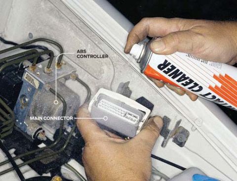
Fuse okay? Check the service manual for the voltage and resistance values on various pins and sensors. The main harness to the ABS controller is one place you'll be checking, so while it's apart, give it a shot of aerosol contact cleaner. Inspect carefully for any signs of corrosion—remember that the signals traveling down some of these wires are only millivolts and almost any resistance is a major impediment. If you can, check the resistance across the wheel speed sensors.
If the ABS controller looks A-Okay, and unplugging and reinserting the main harness didn't help, it's time to eyeball the wheel speed sensors—especially if your ABS issue started right after a trip through that snowbank at the mall or after a high-speed trip down a gravel road. You may have damaged the wiring leading to the ABS sensors or even the tone wheels or sensors themselves. Tone wheel? The ABS controller needs to know how fast each wheel is rotating. Somewhere on each wheel bearing assembly or axle is a toothed wheel, and there's a magnetic pickup positioned immediately next to it. (Exception: Some rwd vehicles use a three-channel system with the tone wheel built into the rear differential.) Because this assembly is out in the open, it's prone to damage from foreign objects.
Loosen the lug nuts or bolts, block the opposite wheel and jack up the car. (You pickup truck owners may be able to crawl under and check.) Inspect the wheel speed sensor's wiring harness and the sensor itself. Some sensors are integrated fairly well into the hub and aren't prone to damage. Others are simply bolted to stamped brackets. If the sensor is loose or missing, or the wires are damaged, you've found your problem. Check the air gap between the sensor and the tone wheel if it's adjustable—the shop manual will give you a specific distance the sensor is supposed to be spaced from the tone wheel and directions on how to properly set it. On rare occasions, the tone wheel itself will show damage, such as missing teeth or teeth damaged by road debris. On front-wheel-drive cars, this usually means replacing the stub axle, because the tone wheel is machined directly onto the axle. If the harness to the sensor has a connector in the wheel well, pull it apart and check the sensor for continuity with an ohmmeter. The resistance value can be found in the shop manual. Check for shorts to ground as well. Repair any bad wiring, remembering that there's plenty of mud, snow and salt water flying around in the wheel well.
TIME'S UP
If you've checked all the sensors and wiring and the ABS light still glows, it's time to throw in the towel and start looking seriously at the ABS controller, an amalgam of hydraulics and electronics that has, as they say, no user-serviceable parts inside. It is, predictably, expensive. Replace it as a last resort.


Comments
Post a Comment