How A Car Electrical System Works?
Electrical System
Working Of Vehicles Electrical System
Helpful Information
Each vehicle has many fuses that are necessary to safeguard electrical circuits. A fuse is designed to short stopping the voltage flow in the event of a power overload or short circuit. Electrical or wire connectors can vary from a single connector to many wires depending on the application. When performing repairs a wiring schematic is sometimes necessary to trace wires and locate the short too be repaired. Wire and connectors vary in size due to different amperage loads for each application. High amperage circuits are designed with larger components to handle the load without failing.
Maintenance
Common maintenance suggests inspecting electrical connectors that are visible including the battery cables. These connections should be free of corrosion and rust as contaminates hinder the proper operation of electrical circuits. A periodic inspection and test of the battery is necessary to avoid roadside failures. Battery terminals can develop corrosion due to the flow of ions, terminal and cable cleaning is necessary to remedy this condition.
Common Problems
The most common problem with an electrical system is a short circuit which is caused when a wire has rubbed through to ground or an electric motor has shorted internally. Low battery voltage can cause strange problems due to insufficient operating voltage which can cause numerous problems. Because of the nature of wiring connectors they can cause high resistance which causes heat, allowing the connector to short and not allow the circuit to function.
Step by step instructions on how an automotive electrical system works. This article pertains to all vehicles.
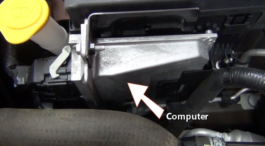
Step 1 - The electrical system of any vehicle performs the same function, to deliver and monitor electrical power to various devices and sensors while under control of acomputer system.

Main Computer
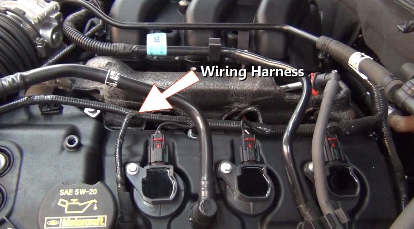
Step 2 - A wiring harness is used to connect various devices and sensors to either control, or send feedback data to the computer. The harness is also used to control the lighting system such as brake lights.

Wiring Harness
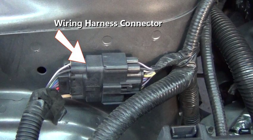
Step 3 - A wiring harness has many connectors that serve as an extension which allows routing to devices which are obscurely located.

Wiring Harness Connector
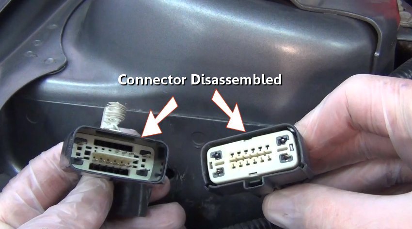
Step 4 - Connectors are disconnected by depressing a small tab on the side of the connector. Once apart, the male side of the connector is designed with terminals that protrude outward, which fit into sockets on the female side. (Note: Some connectors possess a safety tab which must be removed before the connector can be disassembled.)

Electrical Connector Disassembled
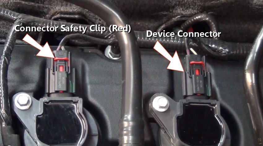
Step 5 - A device connector is used to connect to a particular item such as an ignition coil which is shown here. A safety is used to securely attach the connector to a device, which adds an extra layer of protection from accidental disconnection. This safety clip must be removed before the connector can be released.

Electrical Connector with Safety
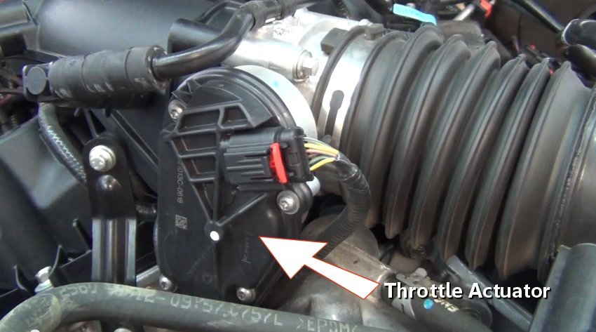
Step 6 - An electronic throttle control actuator is responsible for metering air flow into the engine which control engine RPM (revolutions per minute.) Using a throttle control sensor located near the foot pedal supplies feedback data to the computer. The throttle control system is integrated into the ABS, cruise control and traction control systems. In older vehicles throttle action was performed by a manually controlled throttle cable, which was actuated by the drive's right foot.

Electronic Throttle Actuator
Main Computer
Wiring Harness
Wiring Harness Connector
Electrical Connector Disassembled
Electrical Connector with Safety
Electronic Throttle Actuator
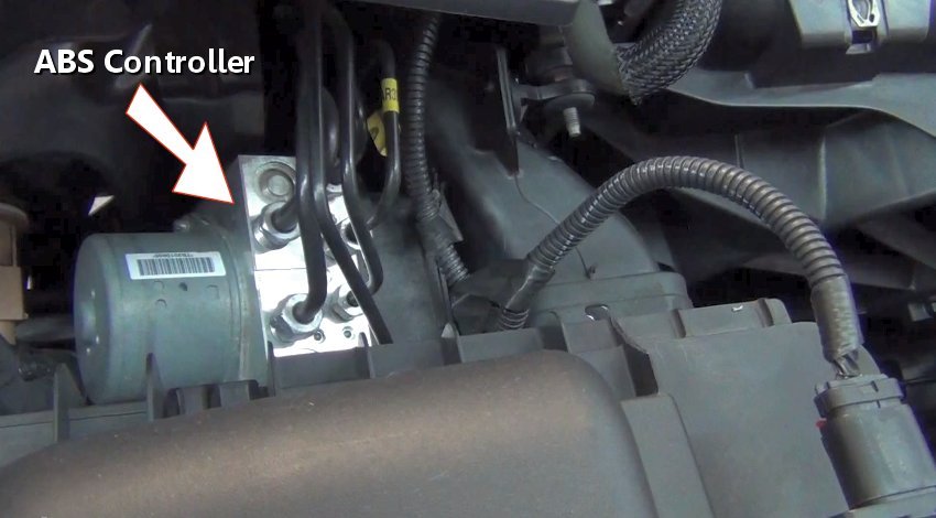
Step 7 - The anti-lock brake systemcontroller is an electronic system that helps prevent the wheels from skidding in panic stop conditions and is integrated into the traction control system.

Anti-Lock Brake System Controller
Step 8 - Sensors provide feedback data to the main computer which in turn will illuminate a warning light or perform an action such as shutting the engine down when engine oil pressure has decreased.
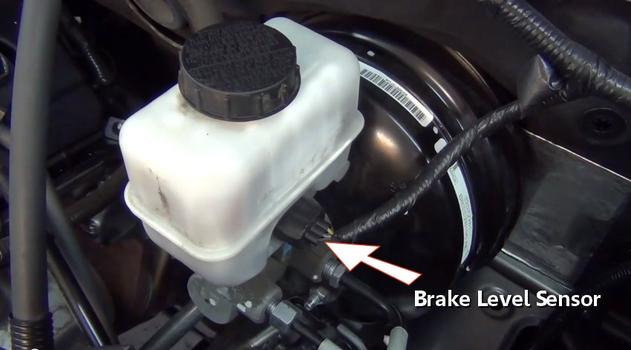
Brake Fluid Level Sensor
Step 9 - Other sensors, such as the camshaft angle sensors use thin metal windings which break a magnetic field as the shaft rotates causing a pulse that is sensed by the computer.
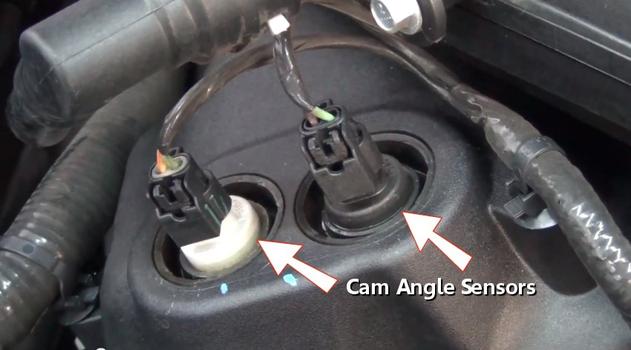
Camshaft Angle Sensors
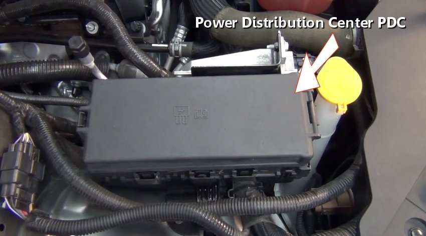
Step 10 - A power distribution center is used to route positive battery power throughout the vehicle via relays and fuses. This center is powered directly off of the positive post of the battery via battery cable.
 Step 11 - Inside the PDC are many fuses and relays which protect and control many electrical circuits such as fuel pump and fuel injection systems.

Fuses and Relays
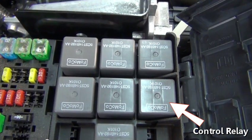
Step 12 - A set of control relays act as the main switching center of electrical power. These relay's act as electronic switches that are controlled by the computer or by a manual switch. Once engaged, the relay connects a circuit which actives a particular device.

Control Relay
Anti-Lock Brake System Controller

Brake Fluid Level Sensor

Camshaft Angle Sensors
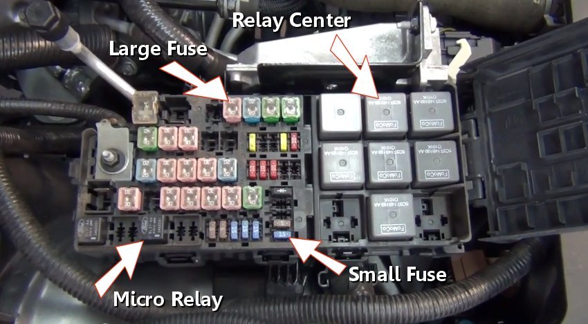
Fuses and Relays
Control Relay
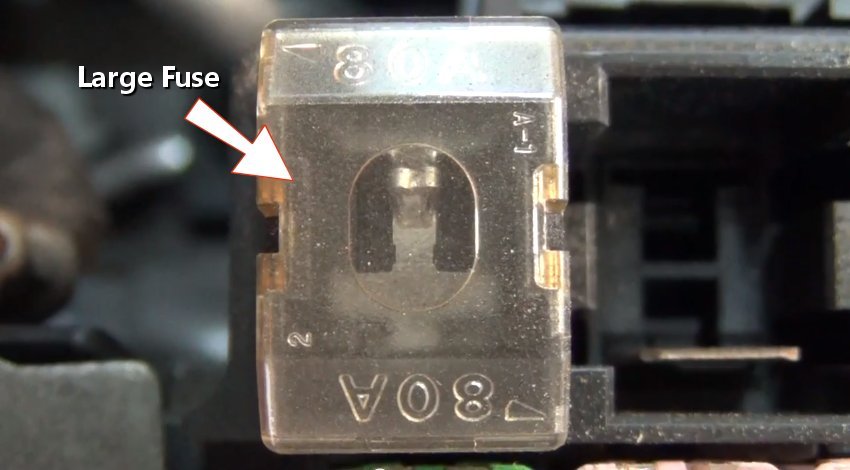
Step 13 - A set of large amperage fuses protect high amperage circuits such as the cooling fan, starter solenoid and headlights. A observation window is provided to inspect the fuse integrity.

Large Amperage Fuse
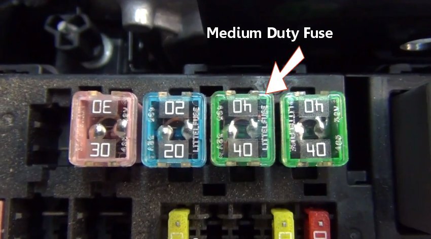
Step 14 - Medium duty fuses are used to protect average vehicle amperage such as power windows and seat heaters. These fuses also provide an observation window which is needed for inspection.

Medium Duty Fuse
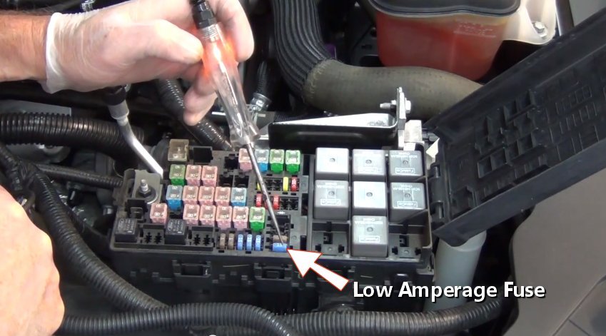
Step 15 - Finally low amperage fuses are used to protect smaller amperage circuits such as tail lights and interior lighting. These fuses are easily checked using a test light.

Low Amperage Fuse
Step 16 - The battery supplies both positive and ground circuits which complete the electron cycle, the positive circuit starts at the PDC via the battery.
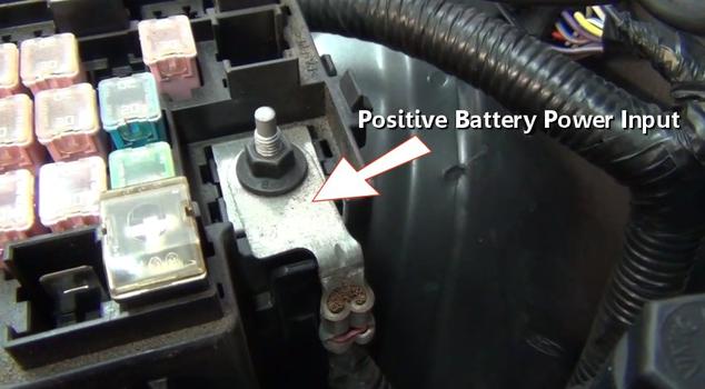
Positive Battery Input
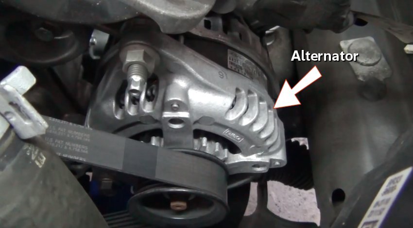
Step 17 - The alternator is powered by the engine via a serpentine belt. This unit creates electrical power by utilizing an armature and copper windings which are connected using brushes. While in operation (engine running) this unit supplies power for the vehicle while charging the battery.
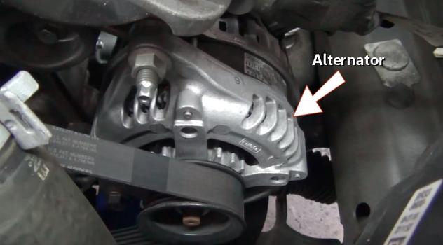
Alternator
Step 18 - The starter motor is designed to turn the engine over when the ignition switch is activated. This device pulls the most amperage of all components encompassed within a vehicle, (hybrid and electric vehicles excluded.)

Starter Motor
Large Amperage Fuse
Medium Duty Fuse
Low Amperage Fuse
Step 16 - The battery supplies both positive and ground circuits which complete the electron cycle, the positive circuit starts at the PDC via the battery.

Positive Battery Input
Alternator

Starter Motor


Comments
Post a Comment