How A Car Engine Works?
Engine
Working Of Car Engine
Helpful Information
- Neglect of scheduled oil changes result in premature engine failures
- Cooling system neglect causing overheating resulting in premature engine failures
Step by step guide on how an automotive internal combustion engine works. This article information pertains to all vehicles except electric.
Step 1 - An internal combustion engine is designed to compress and combust a fuel air mixture which is controlled by the driver.

Automotive Internal Combustion Engine Cutaway
Step 2 - The engine begins by pulling air through the air intake throttle actuator which is controlled via the computer, and foot actuator that is located in the drivers compartment. This air flow is monitored by the mass air flow sensor and cleaned by the air filter.

Electronic Throttle Actuator
Step 3 - Once air has passed through the throttle actuator, it enters the intake manifold were it is divided among individual cylinder intake ports.

Intake Manifold
Step 4 - Air is then routed through the intake manifold were it enters individual intake ports contained within the cylinder head, which is controlled by a valve (intake.)
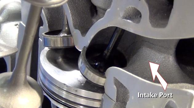
Intake Port Cutaway
Step 5 - Fuel enters the intake port or directly into the combustion chamber via afuel injector which is controlled by the computer.

Port Fuel Injector
Step 6 - A camshaft is used to open each valve while it rotates as the engine is operating. A spring returns the valve to the closed position which is called a "valve spring". (Overhead camshaft configuration shown.)

Camshaft

Automotive Internal Combustion Engine Cutaway
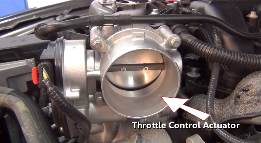
Electronic Throttle Actuator
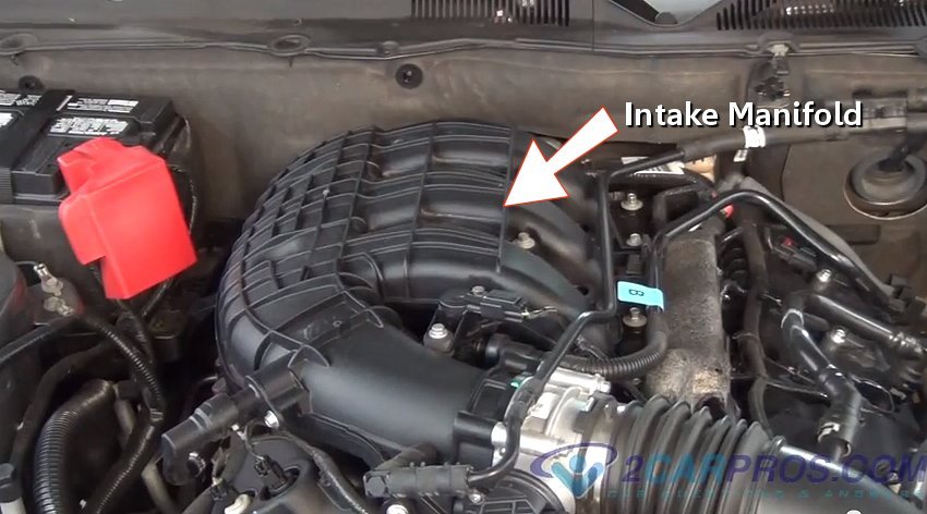
Intake Manifold
Step 4 - Air is then routed through the intake manifold were it enters individual intake ports contained within the cylinder head, which is controlled by a valve (intake.)

Intake Port Cutaway

Port Fuel Injector
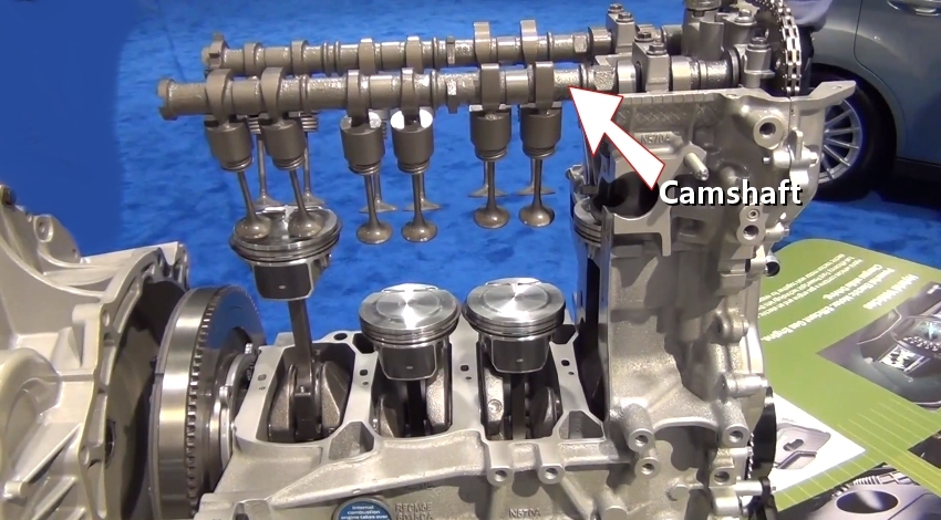
Camshaft
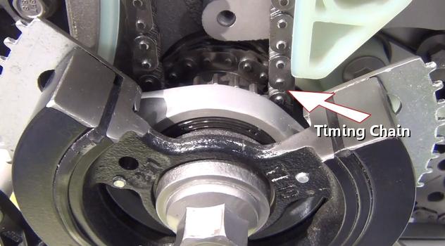
Step 7 - The camshaft is connected to the engine crankshaft via a timing chain. As the crankshaft turns, the chain is pulled while turning the camshaft at a 2 to 1 ratio 2:1. (Crankshaft turns twice to once of the camshaft.) A camshaft actuatoris used to control the angle in which the camshaft is positioned compared to the crankshaft. This position is controlled by the computer.

Timing Chain
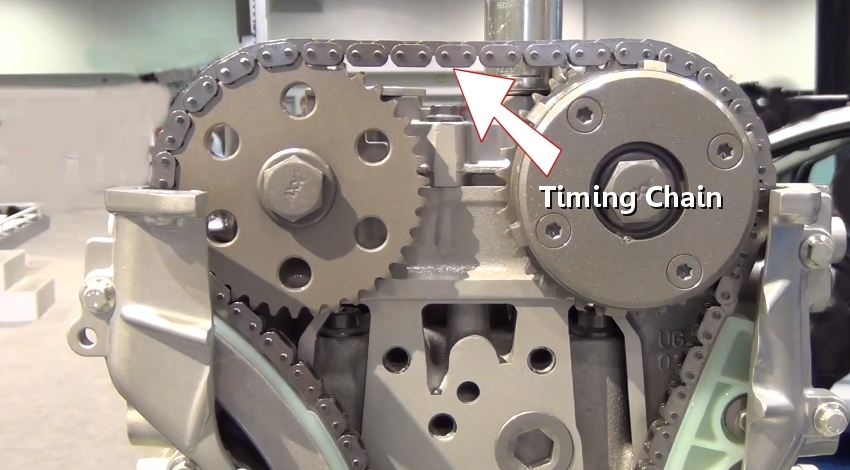
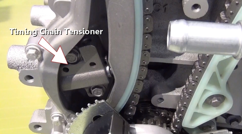
Step 8 - A timing chain tensioner is used to take up slack which helps keep the chain tensioned. This tensioner is activated by engine oil pressure.

Timing Chain Tensioner
Step 9 - The timing chain is driven at the crankshaft using a drive gear near the front seal and harmonic balancer.
Crankshaft Driven Timing Chain
Step 10 - Once the fuel air mixture has entered the combustion chamber the piston is thrust upward compressing the mixture for ignition.
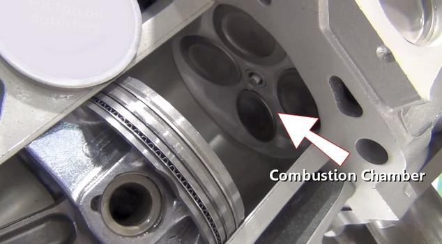
Combustion Chamber Cutaway
Step 11 - After the fuel air mixture is compressed, an ignition coil supplies a high voltage, low amperage charge to the spark plug.
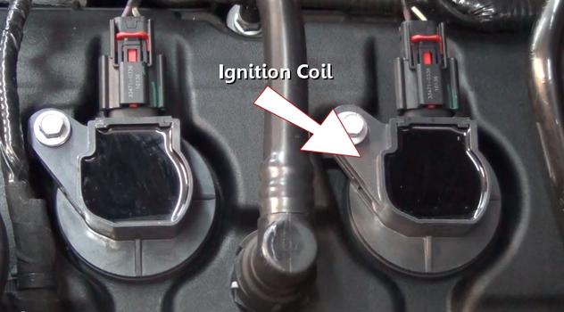
Ignition Coil
Timing Chain
Timing Chain Tensioner

Crankshaft Driven Timing Chain
Step 10 - Once the fuel air mixture has entered the combustion chamber the piston is thrust upward compressing the mixture for ignition.

Combustion Chamber Cutaway

Ignition Coil
Step 12 - This operation is controlled by the computer which gathers data from the crankshaft position sensor(CKS), camshaft angle sensors (CAS) and other various sensors.
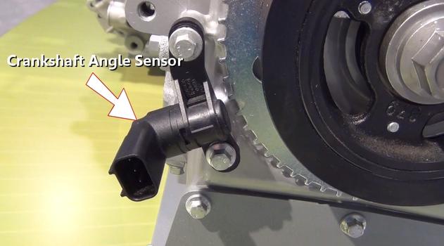
Crankshaft Angle Sensor
Step 13 - After this flammable charge has been compressed, an electronic charge crosses the spark plug, igniting the mixture which then forces the piston downward.

Spark Plug (Block and Cylinder Head Cutaway)
Step 14 - As the piston is thrusting downward the energy is contained within the crankshaft via the piston rods.
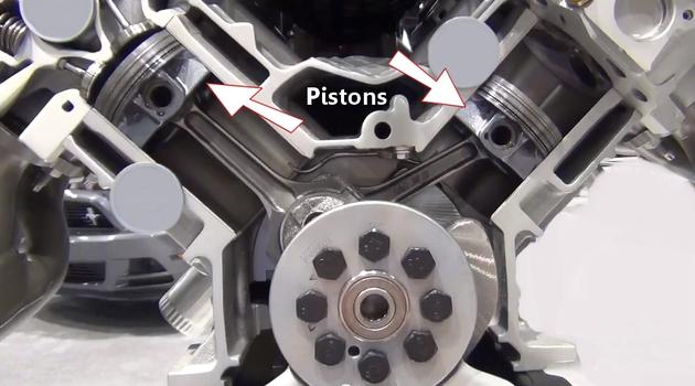
Pistons (Engine Block Cutaway)
Step 15 - The piston rod is designed to transfer energy to a rotating crankshaft which is created by the piston.

Piston Rod
Step 16 - The crankshaft is supported along the engine block and each piston rod attaches to it. Bearings, which are oiled, are then fitted between rotating surfaces.
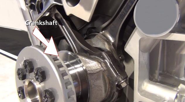
Crankshaft (Block Cutaway)

Crankshaft Angle Sensor

Spark Plug (Block and Cylinder Head Cutaway)
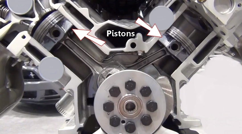
Pistons (Engine Block Cutaway)
Step 15 - The piston rod is designed to transfer energy to a rotating crankshaft which is created by the piston.
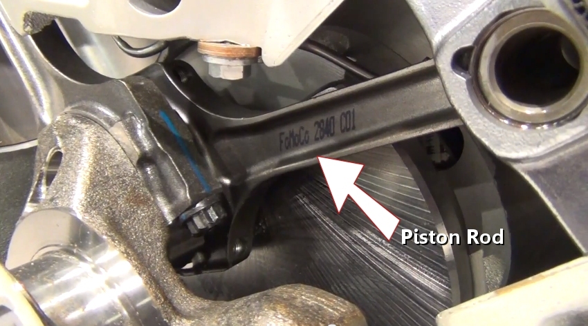
Piston Rod

Crankshaft (Block Cutaway)
Step 17 - Once the intake charge has been spent, the exhaust valve opens while the piston is thrust upward, forcing exhaust gases to be removed from the cylinder and into the exhaust manifold.

Exhaust Valves (Block - Cylinder Head Cutaway)
Step 18 - While the crankshaft is rotating seals are used to control motor oil from leaking from the engine oiling system.
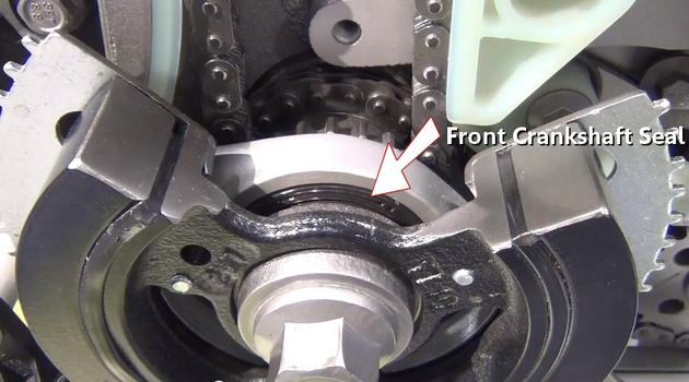
Front Crankshaft Seal
Step 19 - An oil pump is driven from the crankshaft or camshaft and is located in or near the oil pan of the engine. This pump circulates oil under pressure throughout the engine to prevent heat through lubrication among bearing and piston surfaces.
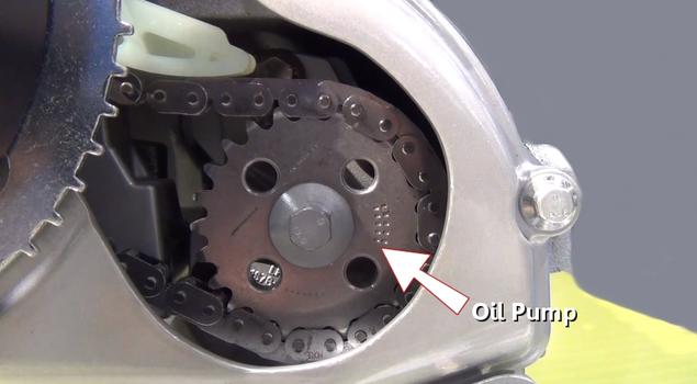
Oil Pump
Step 20 - Oil pressure is monitored by an oil pressure sender, oil is also cleaned by and oil filter which should be serviced regularly.
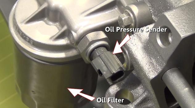
Oil Pressure Sender with Filter
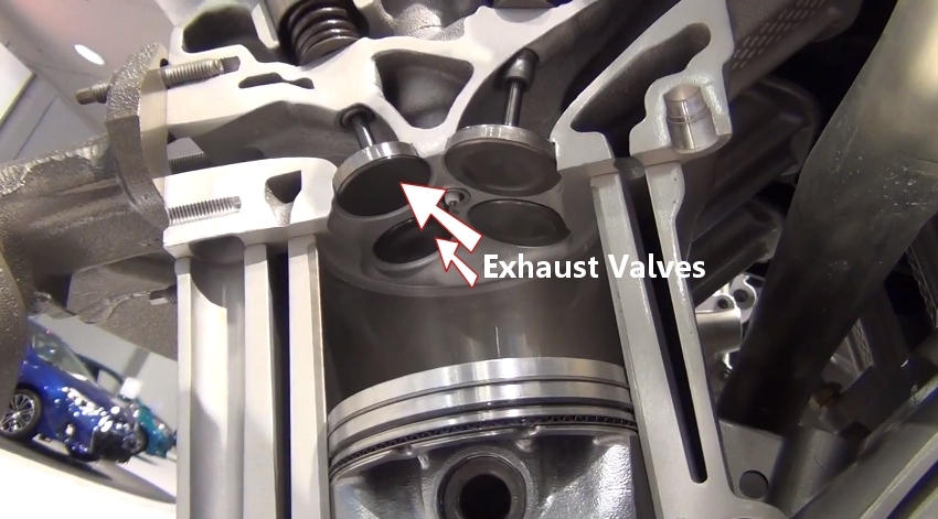
Exhaust Valves (Block - Cylinder Head Cutaway)
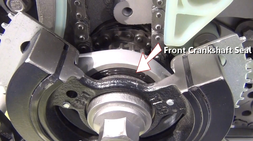
Front Crankshaft Seal

Oil Pump
Step 20 - Oil pressure is monitored by an oil pressure sender, oil is also cleaned by and oil filter which should be serviced regularly.

Oil Pressure Sender with Filter
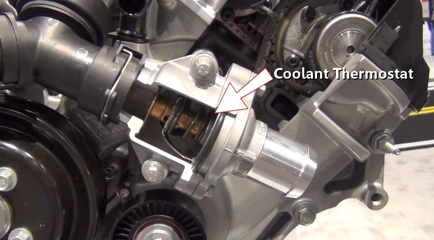
Step 21 - Coolant is used to cool the engine while in operation. Athermostat is used to stop the coolant from flowing to the radiator until the engine is at operating temperature.
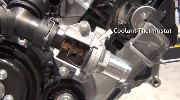
Coolant Thermostat
Step 22 - A water pump is used to circulate coolant throughout the block, cylinder head and cooling system.
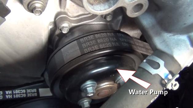
Water Pump
Step 23 - Together these parts create the engine which rotates while consuming fuel.
Coolant Thermostat
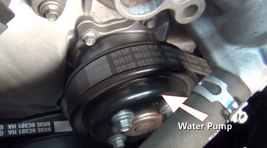
Water Pump


Comments
Post a Comment